A hysteresis comparator offers improved noise immunity by incorporating a slight voltage range between switching thresholds, preventing rapid toggling due to minor signal fluctuations, while a zero crossing detector strictly identifies the point where the input signal crosses zero voltage, useful for timing and phase detection. Understanding these differences helps optimize your circuit design based on noise sensitivity and application needs; explore the rest of the article to learn how to implement each effectively.
Table of Comparison
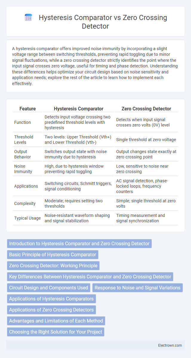
| Feature | Hysteresis Comparator | Zero Crossing Detector |
|---|---|---|
| Function | Detects input voltage crossing two predefined threshold levels with hysteresis | Detects when input signal crosses zero volts (0V) level |
| Threshold Levels | Two levels: Upper Threshold (Vth+) and Lower Threshold (Vth-) | Single threshold at zero voltage |
| Output Behavior | Switches output state with noise immunity due to hysteresis | Output changes state exactly at zero crossing point |
| Noise Immunity | High, due to hysteresis window preventing rapid toggling | Low, sensitive to noise near zero crossing |
| Applications | Switching circuits, Schmitt triggers, signal conditioning | AC signal detection, phase-locked loops, frequency counters |
| Complexity | Moderate; requires setting two thresholds | Simple; single threshold at zero volts |
| Typical Usage | Noise-resistant waveform shaping and signal stabilization | Timing measurement and signal synchronization |
Introduction to Hysteresis Comparator and Zero Crossing Detector
A Hysteresis Comparator is an electronic circuit designed to provide stable switching between high and low output states by incorporating positive feedback, which introduces distinct threshold voltages for rising and falling signals to reduce noise sensitivity. A Zero Crossing Detector, on the other hand, is a specialized comparator that identifies the precise point where an input signal crosses the zero voltage level, facilitating accurate detection of signal polarity changes. Understanding your application's noise immunity requirements and signal characteristics is crucial when choosing between a hysteresis comparator and a zero crossing detector.
Basic Principle of Hysteresis Comparator
The basic principle of a hysteresis comparator involves introducing two different threshold voltage levels, which creates a controlled region of switching to prevent noise-induced rapid toggling in your circuit. Unlike zero crossing detectors that switch output exactly at zero input voltage, hysteresis comparators provide a stable output by incorporating positive feedback to maintain output state until the input crosses distinct upper or lower thresholds. This approach significantly improves noise immunity and output stability in signal processing applications.
Zero Crossing Detector: Working Principle
A Zero Crossing Detector operates by comparing an input signal to a zero voltage reference, switching its output state every time the input crosses the zero voltage level, effectively converting an AC waveform into a digital pulse train. It uses an operational amplifier or comparator with zero bias to identify the exact point where the input voltage changes its polarity. This circuit is essential in phase-locked loops, frequency counters, and waveform shaping, providing precise timing for digital circuits.
Key Differences Between Hysteresis Comparator and Zero Crossing Detector
Hysteresis comparators include a defined hysteresis band to prevent noise-induced switching and provide stable output transitions, while zero crossing detectors switch output exactly when the input signal crosses zero voltage without hysteresis. The hysteresis comparator is ideal for noisy signals requiring noise immunity and signal stability, whereas zero crossing detectors are primarily used to find precise zero voltage points in AC waveform applications. Voltage thresholds in hysteresis comparators create distinct upper and lower switching points, contrasting with zero crossing detectors which have a single, zero-level threshold.
Circuit Design and Components Used
A hysteresis comparator circuit typically incorporates a voltage divider network with positive feedback using resistors to create a distinct upper and lower threshold, preventing noise-induced switching and providing stable output transitions. In contrast, a zero crossing detector employs an operational amplifier or comparator configured without hysteresis, often using just a single resistor and reference ground to identify when the input signal crosses zero volts. The key components defining these designs are the feedback resistors in hysteresis comparators for threshold setting, while zero crossing detectors rely on minimal passive components to detect signal polarity changes.
Response to Noise and Signal Variations
Hysteresis comparators provide enhanced noise immunity by introducing a voltage hysteresis band, which prevents rapid switching near the threshold and stabilizes the output against small signal fluctuations. Zero crossing detectors switch output state precisely at the input zero voltage level but are highly sensitive to noise and minor signal variations, often resulting in multiple unwanted transitions. Therefore, hysteresis comparators are preferred in noisy environments or with slowly varying signals, while zero crossing detectors excel in clean, fast-changing signal detection scenarios.
Applications of Hysteresis Comparators
Hysteresis comparators are widely used in applications requiring noise immunity and stable switching, such as in switch debounce circuits, power supply voltage monitoring, and waveform shaping. Their built-in hysteresis prevents rapid switching caused by small input signal fluctuations, making them ideal for mechanical sensor interfaces and audio signal processing. Unlike zero crossing detectors, which trigger precisely at signal transitions, hysteresis comparators ensure reliable operation in noisy or slowly varying input conditions.
Applications of Zero Crossing Detectors
Zero crossing detectors find extensive use in phase-locked loops, where accurate detection of signal phase transitions is crucial for synchronization. They are also employed in AC waveform measurement instruments to precisely identify the point where the waveform crosses the zero voltage level, enabling accurate frequency and voltage analysis. Additionally, zero crossing detectors enhance switching power supplies by minimizing switching noise through zero-voltage switching techniques.
Advantages and Limitations of Each Method
Hysteresis comparators offer noise immunity and stable switching by introducing a threshold voltage difference, preventing rapid oscillations in noisy signals, making them ideal for applications with slow or noisy input changes. Zero crossing detectors provide precise timing by switching at the exact zero voltage point, making them optimal for AC signal processing but can be susceptible to noise near the zero threshold, leading to false triggering. Understanding these characteristics helps you select the appropriate method based on signal stability requirements and noise conditions in your application.
Choosing the Right Solution for Your Project
Choosing between a hysteresis comparator and a zero crossing detector depends on your project's noise tolerance and signal characteristics. A hysteresis comparator offers better noise immunity and stable switching by incorporating a defined threshold window, making it ideal for signals with fluctuations or slow transitions. Zero crossing detectors excel in detecting precise waveform transitions, especially in AC signal processing, but may require additional filtering for noisy environments to ensure accuracy.
Hysteresis Comparator vs Zero Crossing Detector Infographic