Capacitive coupling uses a capacitor to transfer AC signals between circuits while blocking DC components, making it ideal for high-frequency applications and signal isolation. Transformer coupling relies on magnetic induction to transfer energy, providing galvanic isolation and impedance matching; explore the differences in performance and use cases to optimize your electronic designs.
Table of Comparison
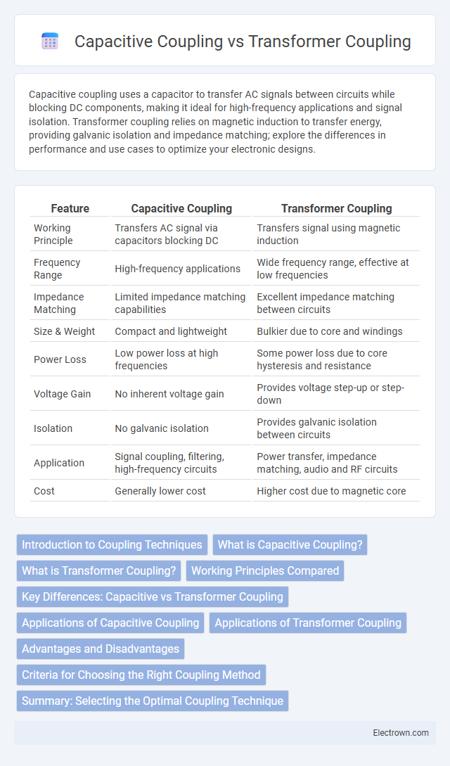
| Feature | Capacitive Coupling | Transformer Coupling |
|---|---|---|
| Working Principle | Transfers AC signal via capacitors blocking DC | Transfers signal using magnetic induction |
| Frequency Range | High-frequency applications | Wide frequency range, effective at low frequencies |
| Impedance Matching | Limited impedance matching capabilities | Excellent impedance matching between circuits |
| Size & Weight | Compact and lightweight | Bulkier due to core and windings |
| Power Loss | Low power loss at high frequencies | Some power loss due to core hysteresis and resistance |
| Voltage Gain | No inherent voltage gain | Provides voltage step-up or step-down |
| Isolation | No galvanic isolation | Provides galvanic isolation between circuits |
| Application | Signal coupling, filtering, high-frequency circuits | Power transfer, impedance matching, audio and RF circuits |
| Cost | Generally lower cost | Higher cost due to magnetic core |
Introduction to Coupling Techniques
Capacitive coupling transfers signals through electric fields between two conductive plates separated by a dielectric, offering high-frequency response and minimal signal distortion suitable for AC signals. Transformer coupling relies on magnetic induction between primary and secondary windings, providing galvanic isolation and impedance matching ideal for power transfer and audio applications. Both techniques serve critical roles in electronic circuits by facilitating signal transfer while addressing frequency range, isolation, and impedance requirements.
What is Capacitive Coupling?
Capacitive coupling is a method of transferring electrical energy between two circuits through a capacitor, allowing AC signals to pass while blocking DC components. It achieves signal isolation without direct electrical contact, effectively filtering out low-frequency interference and preventing DC bias shifts. Commonly used in amplifier stages and communication systems, capacitive coupling offers compact, lightweight coupling with minimal energy loss compared to transformer coupling.
What is Transformer Coupling?
Transformer coupling uses electromagnetic induction between coils to transfer electrical energy or signals, providing galvanic isolation and impedance matching in circuits. It is widely used in audio amplifiers, power supplies, and radio frequency applications where signal integrity and voltage conversion are essential. Unlike capacitive coupling, transformer coupling can handle a wider frequency range and offers better noise rejection due to magnetic flux linkage.
Working Principles Compared
Capacitive coupling transfers signal energy through an electric field created by a capacitor, allowing AC signals to pass while blocking DC components, which makes it ideal for isolating different DC levels in circuits. Transformer coupling relies on electromagnetic induction between primary and secondary coils to transfer energy, providing galvanic isolation and impedance matching for efficient power transfer. Understanding your circuit's frequency response and isolation needs can help determine whether capacitive or transformer coupling best suits your design.
Key Differences: Capacitive vs Transformer Coupling
Capacitive coupling uses capacitors to transfer AC signals while blocking DC components, making it ideal for high-frequency applications and signal isolation. Transformer coupling relies on magnetic induction between coil windings to transfer energy, offering galvanic isolation and impedance matching in audio and power applications. Your choice depends on factors like frequency range, signal type, and isolation needs, with capacitive coupling favored for signal integrity at high frequencies and transformer coupling preferred for robust isolation and power transfer.
Applications of Capacitive Coupling
Capacitive coupling finds extensive applications in signal transmission between high-frequency circuits, audio equipment, and RF filters due to its ability to block DC components while allowing AC signals to pass. Your electronic designs benefit from capacitive coupling in isolating stages without direct electrical connections, improving signal integrity and reducing interference. It is commonly used in tone controls, amplifiers, and feedback networks where precise signal transfer and impedance matching are crucial.
Applications of Transformer Coupling
Transformer coupling is widely used in audio amplification systems to match impedance between different circuit stages, ensuring maximum power transfer and signal integrity. It is essential in power supplies for electrical isolation and voltage step-up or step-down, enhancing safety and efficiency. Your electronic devices benefit from transformer coupling in radio frequency communication systems for signal isolation and noise reduction.
Advantages and Disadvantages
Capacitive coupling offers advantages such as simplicity, low cost, and effective high-frequency signal transfer, but suffers from limited low-frequency response and potential signal distortion due to capacitive reactance. Transformer coupling provides superior impedance matching, isolation, and efficient power transfer across a wide frequency range, yet involves higher cost, larger size, and potential core saturation issues. Both methods require careful consideration of application-specific parameters like frequency spectrum, power levels, and physical constraints to optimize performance.
Criteria for Choosing the Right Coupling Method
Choosing between capacitive coupling and transformer coupling depends on frequency response, signal integrity, and isolation requirements. Capacitive coupling excels in high-frequency applications with minimal signal distortion but offers limited isolation, while transformer coupling provides galvanic isolation and impedance matching ideal for low to medium frequencies. Factors such as power handling, size constraints, and cost efficiency also influence the optimal coupling method selection.
Summary: Selecting the Optimal Coupling Technique
Capacitive coupling offers high-frequency signal transmission with minimal distortion, making it ideal for audio and RF applications, while transformer coupling provides electrical isolation and impedance matching, essential for power transfer and noise reduction. Capacitive coupling excels in compact, low-cost designs but is limited by capacitor tolerance and frequency response, whereas transformer coupling supports wide frequency ranges with robustness at the cost of increased size and weight. Choosing the optimal coupling technique depends on application-specific requirements such as bandwidth, isolation, size constraints, and cost efficiency.
capacitive coupling vs transformer coupling Infographic