Cascode circuits offer improved bandwidth and reduced input-output capacitance compared to cascade configurations, making them ideal for high-frequency amplification. Explore the rest of the article to understand how these differences impact your circuit design choices.
Table of Comparison
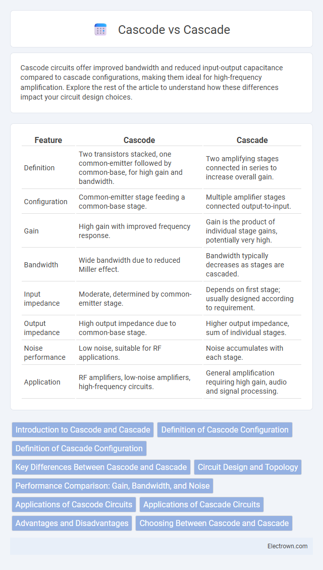
| Feature | Cascode | Cascade |
|---|---|---|
| Definition | Two transistors stacked, one common-emitter followed by common-base, for high gain and bandwidth. | Two amplifying stages connected in series to increase overall gain. |
| Configuration | Common-emitter stage feeding a common-base stage. | Multiple amplifier stages connected output-to-input. |
| Gain | High gain with improved frequency response. | Gain is the product of individual stage gains, potentially very high. |
| Bandwidth | Wide bandwidth due to reduced Miller effect. | Bandwidth typically decreases as stages are cascaded. |
| Input impedance | Moderate, determined by common-emitter stage. | Depends on first stage; usually designed according to requirement. |
| Output impedance | High output impedance due to common-base stage. | Higher output impedance, sum of individual stages. |
| Noise performance | Low noise, suitable for RF applications. | Noise accumulates with each stage. |
| Application | RF amplifiers, low-noise amplifiers, high-frequency circuits. | General amplification requiring high gain, audio and signal processing. |
Introduction to Cascode and Cascade
Cascode and cascade configurations are fundamental amplifier topologies used in analog circuit design to enhance performance parameters such as gain and bandwidth. A cascode amplifier involves a common-emitter stage feeding into a common-base stage, which reduces the Miller effect and improves high-frequency response. In contrast, a cascade configuration consists of multiple amplifier stages connected in series, increasing overall gain but often intensifying the Miller capacitance impact.
Definition of Cascode Configuration
Cascode configuration is a two-stage amplifier design that combines a common-emitter (or common-source) input stage with a common-base (or common-gate) output stage to improve frequency response and gain stability. This topology minimizes the Miller effect, enhancing bandwidth and reducing distortion compared to a simple cascade of two amplifiers. Cascode amplifiers are widely used in radio frequency (RF) and high-speed analog circuits for their superior input-output isolation and high gain-bandwidth product.
Definition of Cascade Configuration
A cascade configuration connects multiple amplifier stages in series, where the output of one stage feeds directly into the input of the next, enhancing overall gain and bandwidth. Cascade circuits are widely used in analog signal processing to amplify weak signals progressively without significant distortion. Your choice between cascade and cascode configurations depends on the desired gain, frequency response, and noise performance of the system.
Key Differences Between Cascode and Cascade
Cascode and cascade amplifier configurations differ primarily in their structure and performance characteristics: cascode uses a common-emitter stage followed by a common-base stage to reduce Miller effect and improve bandwidth, while cascade connects stages sequentially without specific input-output isolation, often resulting in higher gain but lower bandwidth. The cascode topology enhances output impedance and gain stability, making it ideal for RF applications, whereas cascade amplifiers are simpler but can suffer from increased noise and distortion. Understanding these distinctions helps optimize Your circuit design for specific frequency and gain requirements.
Circuit Design and Topology
Cascode and cascade circuit designs differ primarily in their topology and performance benefits; a cascode topology combines a common-emitter (or common-source) stage with a common-base (or common-gate) stage to enhance gain, bandwidth, and reduce Miller effect, while a cascade simply stacks two amplifier stages to increase overall voltage gain. Cascode circuits are favored in high-frequency and low-noise applications due to their superior isolation and stability, whereas cascade topologies are common in general-purpose signal amplification where gain is prioritized without stringent bandwidth requirements. Your choice between cascode and cascade topology impacts noise performance, input-output isolation, and the achievable frequency response in analog integrated circuits.
Performance Comparison: Gain, Bandwidth, and Noise
The cascode configuration provides higher gain and significantly improved bandwidth compared to the cascade arrangement due to its ability to reduce the Miller effect, resulting in enhanced frequency response. Noise performance in a cascode amplifier is superior because the input transistor operates at low voltage gain, minimizing noise contribution, whereas cascade stages accumulate noise from each amplifier. Overall, the cascode structure outperforms traditional cascades in high-frequency applications demanding low noise and wide bandwidth while maintaining substantial gain.
Applications of Cascode Circuits
Cascode circuits are widely applied in RF amplifiers to enhance gain and bandwidth while reducing Miller effect capacitance, making them ideal for high-frequency applications such as wireless communication and radar systems. They are also used in low-noise amplifiers (LNAs) to improve signal integrity by minimizing input capacitance and boosting linearity. In analog integrated circuits, cascode configurations enable stable current mirrors and operational amplifiers with high output impedance and improved frequency response.
Applications of Cascade Circuits
Cascade circuits are widely used in amplification systems to increase overall gain while maintaining bandwidth and stability, making them ideal in audio amplifiers and RF signal processing. These configurations enable thermal stability and reduce distortion, which is critical in high-fidelity audio equipment and communication devices. The straightforward design and scalability of cascaded stages allow for precise control of gain distribution in multi-stage amplifiers, enhancing performance in instrumentation and sensor signal conditioning.
Advantages and Disadvantages
Cascode amplifiers offer advantages such as higher gain, improved bandwidth, and better isolation between input and output stages compared to cascade amplifiers, which can suffer from Miller effect limitations. Cascade configurations are simpler to design and provide moderate gain increases but may experience more noise and reduced frequency response. Choosing between cascode and cascade topologies depends on your specific requirements for gain, bandwidth, and noise performance in electronic circuit design.
Choosing Between Cascode and Cascade
Choosing between cascode and cascade amplifier configurations depends on your specific application needs, such as gain, bandwidth, and noise performance. Cascode amplifiers offer higher gain and improved bandwidth with better isolation between stages, making them ideal for high-frequency and low-noise requirements. Cascade amplifiers provide moderate gain with simplicity, suitable for low-frequency or less demanding applications.
Cascode vs cascade Infographic