Emitter follower and collector follower are transistor configurations that provide voltage buffering with high input and low output impedance, but the emitter follower offers better linearity and is more commonly used for impedance matching. Understanding the distinctions between these two can help optimize your circuit's performance--read on to explore their characteristics and applications in detail.
Table of Comparison
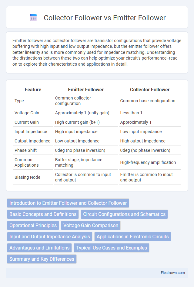
| Feature | Emitter Follower | Collector Follower |
|---|---|---|
| Type | Common-collector configuration | Common-base configuration |
| Voltage Gain | Approximately 1 (unity gain) | Less than 1 |
| Current Gain | High current gain (b+1) | Approximately 1 |
| Input Impedance | High input impedance | Low input impedance |
| Output Impedance | Low output impedance | High output impedance |
| Phase Shift | 0deg (no phase inversion) | 0deg (no phase inversion) |
| Common Applications | Buffer stage, impedance matching | High-frequency amplification |
| Biasing Node | Collector is common to input and output | Emitter is common to input and output |
Introduction to Emitter Follower and Collector Follower
Emitter follower, also known as common-collector amplifier, provides high input impedance and low output impedance, making it ideal for impedance matching in electronic circuits. Collector follower, or common-base amplifier, features low input impedance and high voltage gain but lacks current gain, primarily used in high-frequency applications. Both configurations play crucial roles in signal buffering and amplification with distinctive electrical characteristics.
Basic Concepts and Definitions
An emitter follower is a transistor configuration where the output voltage follows the input voltage with a slight shift, providing high input impedance and low output impedance, ideal for impedance matching. A collector follower, often called a common-base configuration, offers voltage gain with low input impedance and high output impedance, primarily used for current buffering. Understanding these basic concepts helps you select the right transistor follower for your circuit's impedance and gain requirements.
Circuit Configurations and Schematics
The emitter follower circuit configuration features a transistor with the input signal applied to the base and the output taken from the emitter, providing a voltage gain close to unity and offering high input impedance alongside low output impedance. Conversely, the collector follower, often known as a common-base configuration, has the input signal applied to the emitter with the output taken from the collector, resulting in low input impedance and high voltage gain. Schematics for emitter followers typically show the load connected to the emitter terminal, whereas collector follower circuits display the load connected at the collector terminal, highlighting their distinct operational characteristics.
Operational Principles
The emitter follower operates by using the transistor's emitter as the output, providing a voltage gain close to unity with high input impedance and low output impedance, which makes it ideal for impedance matching. In contrast, the collector follower, also known as the common base configuration, outputs from the collector and offers current gain with low input impedance and high output impedance, making it suitable for high-frequency applications. The emitter follower stabilizes voltage levels by following the input voltage minus the base-emitter voltage drop, while the collector follower maintains a constant voltage at the base, allowing for rapid signal amplification.
Voltage Gain Comparison
Emitter followers provide a voltage gain slightly less than unity, typically around 0.9 to 0.99, ensuring signal buffering with minimal distortion. Collector followers, by contrast, offer a voltage gain very close to or equal to unity but are primarily used for current gain rather than voltage amplification. Understanding these differences helps optimize Your circuit design for voltage stability or current driving capability.
Input and Output Impedance Analysis
Emitter followers exhibit high input impedance and low output impedance, making them ideal for impedance matching and buffering applications. Collector followers generally have lower input impedance and high output impedance due to the direct connection at the collector terminal. This impedance disparity significantly affects signal transfer efficiency and loading effects in amplifier circuits.
Applications in Electronic Circuits
Emitter followers, widely used as voltage buffers, provide high input impedance and low output impedance, making them ideal for impedance matching in amplifier stages and audio circuits. Collector followers, often implemented as common-collector configurations, are utilized in power amplification and switching applications due to their ability to source or sink current efficiently. Both are crucial in designing stable, linear amplifiers and ensuring signal integrity across various electronic circuit applications.
Advantages and Limitations
Emitter followers provide high input impedance and low output impedance, making them ideal for impedance matching and signal buffering. Collector followers, or common-base amplifiers, offer low input impedance and high voltage gain but are less effective for impedance matching. Your choice depends on whether you prioritize voltage gain or impedance characteristics in your circuit design.
Typical Use Cases and Examples
Emitter followers are commonly used in voltage buffering applications due to their high input impedance and low output impedance, ideal for impedance matching in audio amplifiers and signal conditioning circuits. Collector followers, often referred to as common-collector configurations, excel in driving loads requiring stable current, such as in low-frequency power amplifiers and voltage regulators. You will find emitter followers preferred for linear voltage amplification and voltage buffering, whereas collector followers are typically utilized where current gain without voltage gain is crucial.
Summary and Key Differences
The emitter follower, also known as the common-collector amplifier, provides high input impedance and low output impedance, making it ideal for impedance matching and voltage buffering applications. In contrast, the collector follower, or common-base amplifier, offers low input impedance and high voltage gain but no current gain, suited for high-frequency applications requiring voltage amplification. Key differences include the emitter follower's voltage gain close to unity versus the collector follower's significant voltage gain, and the emitter follower's use in buffering compared to the collector follower's role in amplifying voltage signals with minimal phase shift.
emitter follower vs collector follower Infographic