A peak detector captures the maximum amplitude of an input signal and holds it until reset, ensuring you record the highest value over time, while a sample and hold circuit samples the input signal at a specific moment and maintains that sampled voltage for a period. Explore the rest of the article to understand which circuit best suits your application and how each functions in detail.
Table of Comparison
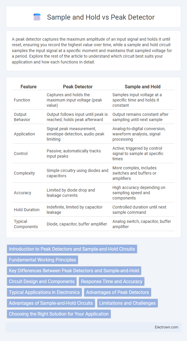
| Feature | Peak Detector | Sample and Hold |
|---|---|---|
| Function | Captures and holds the maximum input voltage (peak value) | Samples input voltage at a specific time and holds it constant |
| Output Behavior | Output follows input until peak is reached; holds peak afterward | Output remains constant after sampling until next sample |
| Application | Signal peak measurement, envelope detection, audio peak limiting | Analog-to-digital conversion, waveform analysis, signal processing |
| Control | Passive; automatically tracks input peaks | Active; triggered by control signal to sample at specific times |
| Complexity | Simple circuitry using diodes and capacitors | More complex, includes switches and buffers or amplifiers |
| Accuracy | Limited by diode drop and leakage currents | High accuracy depending on sampling speed and components |
| Hold Duration | Indefinite, limited by capacitor leakage | Controlled duration until next sample command |
| Typical Components | Diode, capacitor, buffer amplifier | Analog switch, capacitor, buffer amplifier |
Introduction to Peak Detectors and Sample-and-Hold Circuits
Peak detectors capture and hold the maximum voltage level of an input signal for a specific duration, commonly used in signal processing to identify transient signal peaks. Sample-and-hold circuits sample the input voltage at a precise moment and maintain this voltage level for a period, enabling accurate analog-to-digital conversion and signal stabilization. Both components play critical roles in analog electronics, with peak detectors emphasizing maximum value tracking and sample-and-hold circuits focusing on voltage retention for analysis.
Fundamental Working Principles
A peak detector captures and holds the highest voltage level of a varying input signal by charging a capacitor through a diode, effectively tracking signal peaks. A sample and hold circuit samples the input voltage at specific moments, then maintains (holds) this voltage steady for subsequent processing, using a switch and capacitor. Your choice depends on whether you need to monitor peak values continuously or preserve signal amplitude at discrete times for accurate measurement.
Key Differences Between Peak Detectors and Sample-and-Hold
Peak detectors capture and maintain the highest voltage level of an input signal until reset, ideal for measuring signal peaks in applications like RF and audio processing. Sample-and-hold circuits sample an input voltage at a specific moment and preserve this value for a set period, essential for analog-to-digital conversion accuracy. The key difference lies in peak detectors emphasizing maximum signal value retention, whereas sample-and-hold circuits focus on temporarily freezing an instantaneous signal level for measurement or processing.
Circuit Design and Components
Peak detectors typically utilize a diode, capacitor, and operational amplifier to capture and hold the maximum voltage level of a signal, ensuring minimal voltage drop and fast response. Sample and hold circuits employ analog switches or MOSFETs combined with capacitors and op-amps to periodically sample the input voltage and maintain it during the hold phase, emphasizing timing control and low leakage. The choice between these circuits depends on factors such as signal frequency, desired accuracy, and component characteristics like diode forward voltage and capacitor quality.
Response Time and Accuracy
Peak detectors rapidly capture the maximum signal amplitude with minimal delay, offering high response time ideal for transient signals but may suffer from droop affecting long-term accuracy. Sample and hold circuits maintain the sampled signal value over a period, providing stable output for precise measurements with slower response time compared to peak detectors. Accuracy in sample and hold is enhanced by reduced droop and noise, while peak detectors prioritize speed at the cost of potential voltage decay.
Typical Applications in Electronics
Peak detectors are commonly used in RF signal processing and audio level monitoring to capture the maximum amplitude of a rapidly varying signal, ensuring accurate measurement of peak voltage. Sample and hold circuits find typical applications in analog-to-digital converters (ADC) and data acquisition systems, where maintaining a stable voltage during conversion is crucial. Your choice between these depends on whether you need to track transient signal peaks or preserve signal amplitude over a fixed period for processing.
Advantages of Peak Detectors
Peak detectors offer the advantage of capturing the maximum amplitude of a varying signal, providing fast and simple detection without requiring continuous sampling. Their design enables precise tracking of signal peaks, making them ideal for applications like envelope detection and signal strength measurement. Your system benefits from reduced complexity and power consumption compared to sample and hold circuits, which require more components and power to maintain sampled values over time.
Advantages of Sample-and-Hold Circuits
Sample-and-hold circuits offer precise voltage stabilization by capturing and maintaining an analog signal's value for a defined duration, enabling accurate analog-to-digital conversion. Unlike peak detectors, they minimize distortion and noise by isolating the sampled signal from subsequent processing stages. Your data acquisition systems benefit from improved signal integrity and timing control when using sample-and-hold circuits.
Limitations and Challenges
Peak detectors often struggle with inaccuracies due to diode forward voltage drops and temperature variations, which can distort the true signal peak. Sample and hold circuits face challenges related to capacitor leakage and finite hold step errors, resulting in signal degradation during the hold phase. Both systems require careful component selection and design trade-offs to balance speed, accuracy, and stability in high-frequency applications.
Choosing the Right Solution for Your Application
Peak detectors capture and maintain the highest signal level within a given period, ideal for applications requiring monitoring of maximum amplitude, such as audio peak limiting or envelope detection. Sample and hold circuits store a precise voltage level at a specific moment, making them suitable for analog-to-digital conversion, data acquisition, and synchronous sampling systems. Selecting between them depends on whether your application demands continuous peak tracking or stable voltage retention for accurate measurement and processing.
peak detector vs sample and hold Infographic