An emitter follower and a voltage follower both serve as buffer stages with high input impedance and low output impedance, but the emitter follower uses a bipolar junction transistor (BJT) providing current gain, while the voltage follower employs an operational amplifier for voltage buffering with unity gain. Understanding these differences can help you optimize your circuit design; read on to explore their distinct characteristics and applications.
Table of Comparison
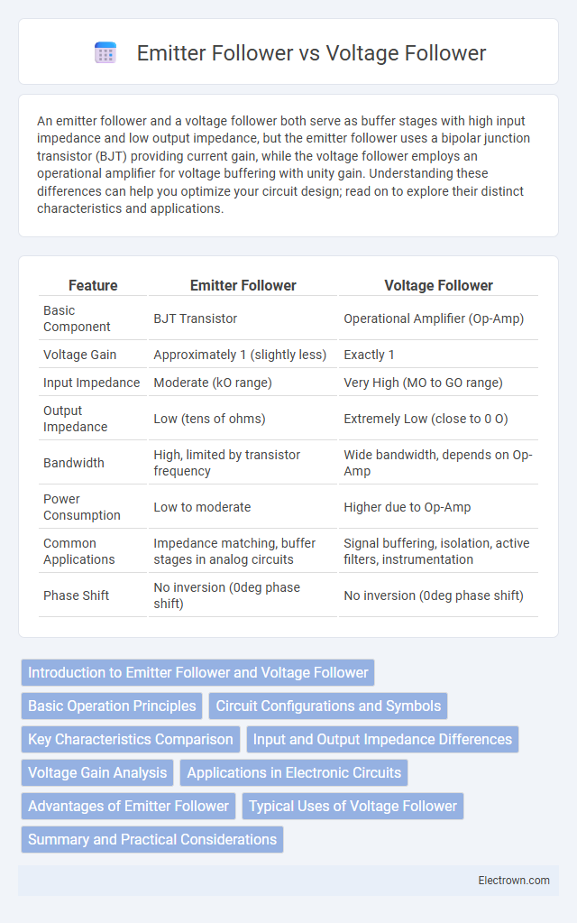
| Feature | Emitter Follower | Voltage Follower |
|---|---|---|
| Basic Component | BJT Transistor | Operational Amplifier (Op-Amp) |
| Voltage Gain | Approximately 1 (slightly less) | Exactly 1 |
| Input Impedance | Moderate (kO range) | Very High (MO to GO range) |
| Output Impedance | Low (tens of ohms) | Extremely Low (close to 0 O) |
| Bandwidth | High, limited by transistor frequency | Wide bandwidth, depends on Op-Amp |
| Power Consumption | Low to moderate | Higher due to Op-Amp |
| Common Applications | Impedance matching, buffer stages in analog circuits | Signal buffering, isolation, active filters, instrumentation |
| Phase Shift | No inversion (0deg phase shift) | No inversion (0deg phase shift) |
Introduction to Emitter Follower and Voltage Follower
The emitter follower, also known as a common-collector amplifier, is a transistor circuit configuration that provides high input impedance and low output impedance, making it ideal for impedance matching. The voltage follower, typically implemented using an operational amplifier, offers unity gain with the primary function of buffering voltage signals without amplification. Both circuits serve as buffer stages, but the emitter follower relies on bipolar junction transistors (BJTs), while the voltage follower uses op-amps for voltage buffering in analog signal processing.
Basic Operation Principles
An emitter follower is a transistor-based circuit where the output voltage follows the input voltage minus a transistor's base-emitter voltage drop, typically around 0.7V for silicon BJTs. A voltage follower, often implemented using an operational amplifier, provides a unity gain buffer that replicates the input voltage at the output without any voltage drop. Your choice between these depends on the need for impedance matching and voltage accuracy in your application.
Circuit Configurations and Symbols
Emitter follower circuits feature a bipolar junction transistor (BJT) with the input signal applied to the base, the output taken from the emitter, and the collector connected to a constant voltage, typically the supply rail, symbolized by a transistor symbol with the emitter as the output terminal. Voltage follower configurations use operational amplifiers with the output connected directly to the inverting input and the input signal applied to the non-inverting input, represented by a triangle symbol with input and output terminals clearly marked for unity gain operation. The emitter follower symbol emphasizes the transistor's three terminals (base, collector, emitter), while the voltage follower symbol highlights the feedback loop ensuring the output voltage equals the input voltage.
Key Characteristics Comparison
An emitter follower is a bipolar junction transistor (BJT) configuration characterized by high input impedance and low output impedance, providing current gain but no voltage gain, making it ideal for impedance matching. A voltage follower, often realized using an operational amplifier, offers unity voltage gain with very high input impedance and very low output impedance, resulting in excellent voltage buffering without signal distortion. Both circuits serve to transfer signals with minimal voltage loss, but the emitter follower excels in current amplification, while the voltage follower prioritizes voltage stability and signal integrity.
Input and Output Impedance Differences
An emitter follower, built using a bipolar junction transistor (BJT), typically exhibits a moderate input impedance ranging from several kilo-ohms to mega-ohms and a low output impedance around tens of ohms, making it suitable for buffering applications with moderate impedance matching. In contrast, a voltage follower implemented with an operational amplifier (op-amp) features an extremely high input impedance, often in the mega-ohms to giga-ohms range, and an exceptionally low output impedance typically under one ohm, ideal for driving low-impedance loads without signal degradation. These impedance characteristics impact their use cases, where emitter followers excel in moderate impedance buffering and voltage followers provide superior buffering with minimal signal loss and high linearity.
Voltage Gain Analysis
Voltage gain analysis reveals that an emitter follower typically has a voltage gain slightly less than 1 due to the transistor's base-emitter voltage drop, commonly around 0.7V, resulting in a gain of approximately 0.9 to 0.99. A voltage follower, specifically an operational amplifier configured as a buffer, provides an almost ideal voltage gain of exactly 1, minimizing signal attenuation. Understanding these differences is critical for your circuit design when precise voltage buffering or impedance matching is required.
Applications in Electronic Circuits
Emitter followers and voltage followers are widely used in electronic circuits to provide impedance matching and buffer signals without significant voltage gain. Emitter followers, based on bipolar junction transistors, excel in driving low-impedance loads and isolating stages, making them ideal for power amplifiers and audio circuits. Voltage followers, typically implemented with operational amplifiers, offer high input impedance and low output impedance, perfect for sensor signal buffering, analog-to-digital conversion, and precision voltage buffering in measurement systems. Your choice depends on the specific impedance, gain, and linearity requirements of your application.
Advantages of Emitter Follower
Emitter followers offer high input impedance and low output impedance, making them ideal for impedance matching in amplifier circuits. They provide voltage gain close to unity while delivering substantial current gain, which improves signal driving capability without distortion. This configuration enhances linearity and stability, resulting in efficient buffering and reduced signal loss compared to standard voltage followers.
Typical Uses of Voltage Follower
Voltage followers are commonly used as buffer amplifiers to provide high input impedance and low output impedance, ensuring signal integrity without loading the source. They are ideal for impedance matching in audio circuits, sensor signal conditioning, and analog-to-digital converter inputs. In contrast, emitter followers are often utilized in transistor-based circuits for current amplification and voltage buffering with slight voltage drop.
Summary and Practical Considerations
The emitter follower, a transistor-based buffer, provides high input impedance and low output impedance, making it ideal for impedance matching in analog circuits. The voltage follower, typically implemented using an operational amplifier, offers unity gain and minimal signal distortion, excelling in voltage buffering applications that require precise voltage replication. Practical considerations include the emitter follower's limited voltage gain and dependence on transistor biasing versus the voltage follower's power supply requirements and potential bandwidth limitations.
Emitter follower vs voltage follower Infographic