An integrator op-amp circuit produces an output voltage proportional to the integral of the input signal, effectively summing the input over time, while a differentiator op-amp outputs a voltage proportional to the rate of change of the input signal, highlighting rapid variations. Understanding these fundamental differences in op-amp configurations is essential for designing analog signal processing applications; explore the rest of this article to deepen your knowledge of integrators and differentiators.
Table of Comparison
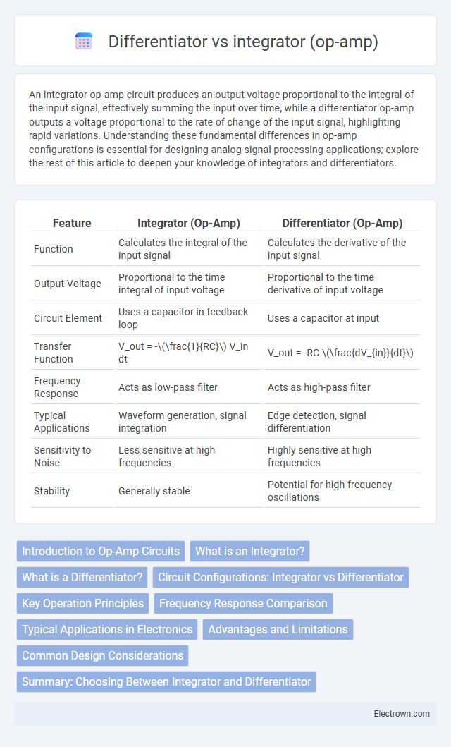
| Feature | Integrator (Op-Amp) | Differentiator (Op-Amp) |
|---|---|---|
| Function | Calculates the integral of the input signal | Calculates the derivative of the input signal |
| Output Voltage | Proportional to the time integral of input voltage | Proportional to the time derivative of input voltage |
| Circuit Element | Uses a capacitor in feedback loop | Uses a capacitor at input |
| Transfer Function | V_out = -\(\frac{1}{RC}\) V_in dt | V_out = -RC \(\frac{dV_{in}}{dt}\) |
| Frequency Response | Acts as low-pass filter | Acts as high-pass filter |
| Typical Applications | Waveform generation, signal integration | Edge detection, signal differentiation |
| Sensitivity to Noise | Less sensitive at high frequencies | Highly sensitive at high frequencies |
| Stability | Generally stable | Potential for high frequency oscillations |
Introduction to Op-Amp Circuits
Op-amp circuits perform mathematical operations such as integration and differentiation on input signals, transforming them into corresponding output waveforms. An integrator op-amp circuit produces an output proportional to the integral of the input voltage, ideal for signal conditioning and waveform shaping. Your choice between an integrator and a differentiator depends on whether you need to accumulate signal values over time or detect rapid signal changes.
What is an Integrator?
An integrator in op-amp circuits is a configuration that produces an output voltage proportional to the integral of the input voltage over time, effectively performing mathematical integration. It typically uses a resistor and a capacitor in the feedback loop, where the capacitor accumulates charge corresponding to the input signal, resulting in an output that represents the accumulated area under the input waveform. Integrators are essential in analog computing, signal processing, and waveform generation applications due to their ability to convert voltage signals into time-integrated outputs.
What is a Differentiator?
A differentiator op-amp circuit produces an output voltage proportional to the rate of change, or derivative, of the input voltage with respect to time. It amplifies rapid changes in the input signal, making it useful for edge detection and signal processing applications. The output voltage V_out can be expressed as V_out = -RC dV_in/dt, where R and C are the resistor and capacitor values in the feedback loop.
Circuit Configurations: Integrator vs Differentiator
Integrator circuits use an op-amp with a resistor connected to the input and a capacitor in the feedback loop, creating an output proportional to the time integral of the input signal. Differentiator circuits reverse this configuration, placing a capacitor at the input and a resistor in the feedback path, producing an output proportional to the rate of change of the input voltage. Understanding these distinct configurations enables you to design signal processing applications tailored for integration or differentiation tasks effectively.
Key Operation Principles
An integrator op-amp produces an output voltage proportional to the integral of the input voltage, effectively summing the input signal over time through a feedback capacitor. A differentiator op-amp outputs a voltage proportional to the rate of change or derivative of the input voltage, utilizing a feedback resistor and an input capacitor to detect rapid variations. Your choice between an integrator and differentiator depends on whether you need to analyze the cumulative signal or its instantaneous rate of change.
Frequency Response Comparison
The frequency response of an op-amp integrator exhibits a decrease in output amplitude proportional to the inverse of frequency, creating a -20 dB/decade slope characteristic. In contrast, the differentiator's frequency response increases output amplitude linearly with frequency, resulting in a +20 dB/decade slope. These opposing behaviors affect signal processing choices; integrators are ideal for low-frequency signal accumulation, while differentiators excel in high-frequency edge detection.
Typical Applications in Electronics
Integrator op-amps are widely used in analog signal processing for generating ramp signals, waveform shaping, and audio effects like reverb and tremolo. Differentiator circuits excel in edge detection, pulse shaping, and high-frequency noise reduction in communication systems. Your choice between integrator and differentiator depends on whether you need to accumulate or respond rapidly to changes in input signals.
Advantages and Limitations
Integrator op-amps provide output proportional to the integral of the input signal, making them ideal for waveform generation, signal processing, and analog computation with benefits like noise reduction and smoothing. Differentiator op-amps output the rate of change of the input, useful in edge detection and high-frequency signal analysis, but are more sensitive to noise and require careful component selection. Your choice depends on whether you need time-domain accumulation or rapid response to input changes, balancing the integrator's stability and noise immunity against the differentiator's sensitivity and potential noise amplification.
Common Design Considerations
Integrator and differentiator op-amp circuits require careful selection of resistors and capacitors to ensure stability and minimize noise. The integrator's choice of feedback capacitor and input resistor values directly impacts the time constant and frequency response, while the differentiator demands low parasitic capacitance and proper input resistor sizing to avoid high-frequency oscillations. Your design must also address the op-amp's bandwidth and slew rate to maintain accurate integration or differentiation without signal distortion.
Summary: Choosing Between Integrator and Differentiator
Selecting the right op-amp configuration depends on your signal processing needs: an integrator produces an output proportional to the integral of the input, ideal for waveform generation and low-pass filtering, while a differentiator outputs the derivative, useful for detecting rapid signal changes and edge detection. Integrators excel in noise reduction and smoothing applications, whereas differentiators amplify high-frequency components, which may increase noise sensitivity. Your choice should align with whether your priority is signal accumulation or change detection, ensuring optimal circuit performance and signal fidelity.
Integrator vs differentiator (op-amp) Infographic