P-channel and N-channel FETs differ primarily in charge carriers and voltage polarity; N-channel FETs use electrons and offer higher electron mobility and faster operation, whereas P-channel FETs use holes, making them suitable for high-side switching despite slightly lower performance. Understanding these differences is crucial for selecting the right transistor in circuit design--continue reading to explore their characteristics and applications in detail.
Table of Comparison
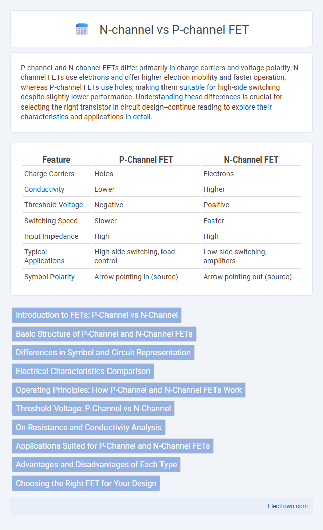
| Feature | P-Channel FET | N-Channel FET |
|---|---|---|
| Charge Carriers | Holes | Electrons |
| Conductivity | Lower | Higher |
| Threshold Voltage | Negative | Positive |
| Switching Speed | Slower | Faster |
| Input Impedance | High | High |
| Typical Applications | High-side switching, load control | Low-side switching, amplifiers |
| Symbol Polarity | Arrow pointing in (source) | Arrow pointing out (source) |
Introduction to FETs: P-Channel vs N-Channel
P-Channel and N-Channel Field-Effect Transistors (FETs) control current flow using an electric field, with N-Channel FETs conducting electrons and P-Channel FETs conducting holes. N-Channel FETs typically exhibit higher electron mobility, resulting in faster switching speeds and lower on-state resistance compared to P-Channel counterparts. Both transistor types are essential in complementary metal-oxide-semiconductor (CMOS) technology, enabling efficient power management and digital logic circuit design.
Basic Structure of P-Channel and N-Channel FETs
P-channel FETs have a substrate made of n-type material with p-type source and drain regions, while N-channel FETs consist of a p-type substrate and n-type source and drain regions. The basic structure impacts their charge carriers, with holes conducting in P-channel devices and electrons in N-channel devices, affecting switching speed and conductivity. Understanding these structural differences helps you select the appropriate FET type for efficient electronic circuit design.
Differences in Symbol and Circuit Representation
P-channel FET symbols feature an arrow pointing inward toward the gate, indicating hole current flow, while N-channel FET symbols have an arrow pointing outward, representing electron flow. In circuit diagrams, the source of a P-channel device is typically connected to a positive voltage supply, whereas the N-channel source is usually tied to ground or a lower potential. These symbol and connection conventions reflect the distinct charge carriers and operating polarities inherent to each FET type.
Electrical Characteristics Comparison
P-channel FETs typically exhibit higher on-resistance and slower switching speeds compared to N-channel FETs due to lower electron mobility in the P-type channel. N-channel FETs offer better conductivity and efficiency, characterized by lower threshold voltages and higher current-carrying capabilities. The drain current in N-channel devices is primarily due to electron flow, while in P-channel devices, it is carried by holes, affecting their respective electrical performance and applications.
Operating Principles: How P-Channel and N-Channel FETs Work
P-channel FETs conduct when a negative voltage is applied to the gate relative to the source, allowing current to flow from source to drain through holes as the majority carriers. N-channel FETs operate with a positive gate-to-source voltage, enabling electron flow from drain to source, which typically offers higher electron mobility and faster switching speeds. Your choice between P-channel and N-channel FETs depends on the required polarity and efficiency in your electronic circuit design.
Threshold Voltage: P-Channel vs N-Channel
N-channel FETs typically have a lower threshold voltage (V_TH) compared to P-channel FETs, making them easier to turn on with less gate voltage. P-channel FETs require a more negative gate voltage relative to the source to reach the threshold and begin conducting. Understanding the differences in threshold voltage between these FET types helps you optimize your circuit design for power efficiency and switching speed.
On-Resistance and Conductivity Analysis
N-channel FETs typically exhibit lower On-Resistance (R_DS(on)) due to higher electron mobility compared to p-channel FETs, making them more efficient for high-current applications. The conductivity of N-channel devices is enhanced by the majority charge carriers being electrons, which have approximately twice the mobility of holes in p-channel FETs. When selecting a transistor for your circuit, understanding that p-channel FETs generally have higher On-Resistance and lower conductivity is crucial for optimizing performance and power efficiency.
Applications Suited for P-Channel and N-Channel FETs
N-channel FETs excel in high-speed switching and low-resistance applications, making them ideal for power supplies, motor controls, and amplifiers due to their higher electron mobility. P-channel FETs are preferred in high-side switch configurations and battery-powered devices where ease of integration into positive voltage rails is crucial despite their lower conductivity compared to N-channel devices. Both types are essential in complementary MOS (CMOS) circuits, leveraging N-channel FETs for pull-down networks and P-channel FETs for pull-up networks to optimize power efficiency and switching performance.
Advantages and Disadvantages of Each Type
N-channel FETs generally offer higher electron mobility, resulting in faster switching speeds and lower on-resistance, making them ideal for high-performance applications. P-channel FETs provide simpler high-side switching and ease of use in complementary circuits but tend to have higher on-resistance and slower operation due to lower hole mobility. Your choice depends on whether performance speed or easier circuit integration is more critical for your design needs.
Choosing the Right FET for Your Design
Selecting the appropriate FET type depends on factors such as switching speed, voltage levels, and circuit polarity. N-channel FETs offer lower on-resistance and higher electron mobility, making them ideal for high-efficiency, low-voltage applications. P-channel FETs are preferred for high-side switching due to their compatibility with positive voltages but typically have slower switching speeds and higher resistance.
p-channel vs n-channel FET Infographic