A common base amplifier provides low input impedance and high voltage gain, making it suitable for high-frequency applications, whereas a common collector amplifier offers high input impedance and unity voltage gain, ideal for impedance matching and buffering. Explore the rest of the article to understand which configuration best suits your electronic circuit needs.
Table of Comparison
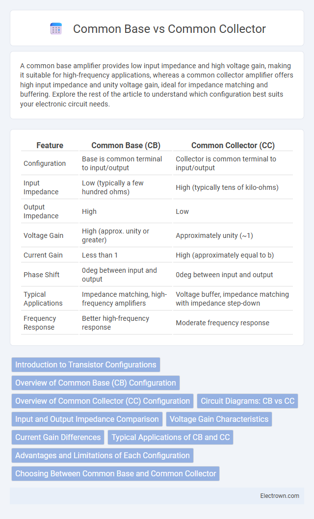
| Feature | Common Base (CB) | Common Collector (CC) |
|---|---|---|
| Configuration | Base is common terminal to input/output | Collector is common terminal to input/output |
| Input Impedance | Low (typically a few hundred ohms) | High (typically tens of kilo-ohms) |
| Output Impedance | High | Low |
| Voltage Gain | High (approx. unity or greater) | Approximately unity (~1) |
| Current Gain | Less than 1 | High (approximately equal to b) |
| Phase Shift | 0deg between input and output | 0deg between input and output |
| Typical Applications | Impedance matching, high-frequency amplifiers | Voltage buffer, impedance matching with impedance step-down |
| Frequency Response | Better high-frequency response | Moderate frequency response |
Introduction to Transistor Configurations
Common base and common collector are two fundamental transistor configurations that define how input and output signals relate within bipolar junction transistors (BJTs). The common base configuration offers low input impedance and high voltage gain, making it ideal for high-frequency applications, while the common collector configuration provides high input impedance and unity voltage gain, often used for impedance matching and buffering. Understanding these configurations enables you to optimize transistor performance based on your circuit's operational requirements.
Overview of Common Base (CB) Configuration
The Common Base (CB) configuration features the base terminal as the common reference point for both input and output signals, providing low input impedance and high output impedance. This setup is known for its excellent frequency response and is often used in high-frequency amplifier circuits. You can enhance circuit stability and gain control by leveraging the CB configuration's unique transistor characteristics.
Overview of Common Collector (CC) Configuration
The common collector (CC) configuration, also known as an emitter follower, features the collector terminal connected to a common reference point, typically ground. It provides high input impedance, low output impedance, and a voltage gain close to unity, making it ideal for impedance matching and buffering applications. The CC configuration effectively transfers signals without significant voltage amplification, maintaining signal integrity while driving low-impedance loads.
Circuit Diagrams: CB vs CC
The Common Base (CB) circuit diagram features the base terminal as grounded or common, with the input signal applied to the emitter and output taken from the collector, emphasizing voltage gain with low input impedance. In contrast, the Common Collector (CC) circuit diagram, also known as the emitter follower, connects the collector to a fixed voltage, applies the input to the base, and outputs from the emitter, providing high input impedance and voltage buffering. Both configurations are fundamental in transistor amplifier design, where CB offers current gain near unity and CC provides voltage gain close to unity with high current gain.
Input and Output Impedance Comparison
Common base amplifiers exhibit low input impedance, typically ranging from 50 to 200 ohms, making them suitable for high-frequency applications where signal source impedance is low. In contrast, common collector amplifiers, also known as emitter followers, present very high input impedance often exceeding 10 kO, allowing for minimal loading on the signal source. Your choice between these configurations depends on whether low input impedance and high output impedance (common base) or high input impedance and low output impedance (common collector) better suit your circuit requirements.
Voltage Gain Characteristics
Common base amplifiers typically exhibit a voltage gain greater than one due to their low input impedance and high output impedance, making them effective for high-frequency applications. Common collector amplifiers, also known as emitter followers, have a voltage gain approximately equal to one, providing voltage buffering and impedance matching without significant amplification. Your choice between the two depends on whether voltage gain or impedance characteristics are more critical in your circuit design.
Current Gain Differences
The common base configuration exhibits a current gain slightly less than unity, typically around 0.95, due to the input current being the emitter current and the output current being the collector current, which is marginally smaller. In contrast, the common collector configuration, also known as the emitter follower, offers current gain significantly greater than one, often ranging from 20 to 200, because the output current at the emitter is the sum of the base and collector currents. This substantial difference in current gain makes the common collector ideal for impedance matching and buffering applications, whereas the common base is mainly used for high-frequency amplification requiring low input impedance.
Typical Applications of CB and CC
Common base (CB) configuration is typically used in high-frequency applications such as RF amplifiers and impedance matching due to its low input impedance and high voltage gain. Common collector (CC), also known as emitter follower, finds frequent use in impedance buffering, voltage regulation, and as a driver stage because of its unity voltage gain and high input impedance. Both configurations serve distinct roles in analog circuit design, with CB excelling in signal amplification at microwave frequencies and CC optimizing signal transfer between stages.
Advantages and Limitations of Each Configuration
The common base configuration offers advantages such as high voltage gain and low input impedance, making it ideal for high-frequency applications, but it suffers from limited input signal range and no current gain. The common collector, or emitter follower, excels in providing high input impedance, low output impedance, and unity voltage gain, which is advantageous for impedance matching and buffering, though it cannot amplify voltage. Understanding these trade-offs helps you select the right transistor configuration for signal amplification or impedance matching needs.
Choosing Between Common Base and Common Collector
Choosing between a common base and common collector configuration depends on the application requirements for input and output impedance as well as voltage and current gain. The common base configuration offers low input impedance and high voltage gain, making it ideal for high-frequency applications and voltage amplification. In contrast, the common collector provides high input impedance and unity voltage gain with high current gain, suited for impedance matching and buffering purposes.
common base vs common collector Infographic