A full wave rectifier uses two diodes and a center-tapped transformer to convert the entire input AC waveform into pulsating DC, while a bridge rectifier employs four diodes arranged in a bridge configuration to achieve full-wave rectification without requiring a center-tapped transformer. Understanding the differences between these rectifiers can help you choose the most efficient circuit for your power supply needs, so continue reading to explore their applications and advantages.
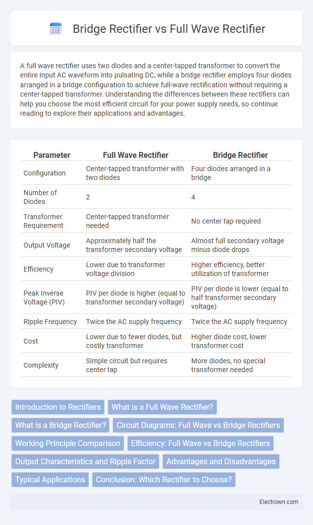
Table of Comparison
| Parameter | Full Wave Rectifier | Bridge Rectifier |
|---|---|---|
| Configuration | Center-tapped transformer with two diodes | Four diodes arranged in a bridge |
| Number of Diodes | 2 | 4 |
| Transformer Requirement | Center-tapped transformer needed | No center tap required |
| Output Voltage | Approximately half the transformer secondary voltage | Almost full secondary voltage minus diode drops |
| Efficiency | Lower due to transformer voltage division | Higher efficiency, better utilization of transformer |
| Peak Inverse Voltage (PIV) | PIV per diode is higher (equal to transformer secondary voltage) | PIV per diode is lower (equal to half transformer secondary voltage) |
| Ripple Frequency | Twice the AC supply frequency | Twice the AC supply frequency |
| Cost | Lower due to fewer diodes, but costly transformer | Higher diode cost, lower transformer cost |
| Complexity | Simple circuit but requires center tap | More diodes, no special transformer needed |
Introduction to Rectifiers
Full wave rectifiers convert the entire input AC signal into a pulsating DC output by using either a center-tapped transformer with two diodes or a bridge circuit with four diodes. Bridge rectifiers, unlike full wave rectifiers with center-tapped transformers, efficiently utilize four diodes without the need for a center tap, providing better voltage output and transformer utilization. Your choice between these depends on factors like transformer design, component count, and voltage requirements.
What is a Full Wave Rectifier?
A full wave rectifier converts the entire alternating current (AC) input into direct current (DC) by utilizing both the positive and negative halves of the AC waveform. It typically employs either a center-tapped transformer with two diodes or a four-diode bridge configuration to achieve full-wave rectification. This process results in a higher average output voltage and improved efficiency compared to half-wave rectifiers.
What is a Bridge Rectifier?
A bridge rectifier is an electronic circuit that converts alternating current (AC) into direct current (DC) using four diodes arranged in a bridge configuration to provide full-wave rectification. Unlike a full wave rectifier that uses a center-tapped transformer and two diodes, the bridge rectifier eliminates the need for a center tap and offers higher efficiency by utilizing both halves of the AC waveform. This makes the bridge rectifier a preferred choice for power supplies delivering smoother and more stable DC output to your electronic devices.
Circuit Diagrams: Full Wave vs Bridge Rectifiers
Full wave rectifiers utilize a center-tapped transformer with two diodes, directing current through each half-cycle to produce a pulsating DC output, clearly illustrated in their circuit diagram. Bridge rectifiers employ four diodes arranged in a bridge configuration, allowing full-wave rectification without the need for a center-tapped transformer, which simplifies the circuit design and enhances efficiency. Understanding these circuit diagrams helps you choose the appropriate rectifier for your application, balancing complexity and performance.
Working Principle Comparison
A full wave rectifier uses a center-tapped transformer and two diodes to convert both halves of the AC input into pulsating DC, allowing current to flow through the load during both positive and negative cycles. In contrast, a bridge rectifier employs four diodes arranged in a bridge configuration, enabling full-wave rectification without the need for a center-tapped transformer by directing current through a path of two diodes during each half cycle. The bridge rectifier typically offers higher output voltage and improved transformer utilization compared to the full wave rectifier due to its more efficient diode arrangement.
Efficiency: Full Wave vs Bridge Rectifiers
A bridge rectifier typically offers higher efficiency compared to a full wave rectifier because it utilizes four diodes to convert both halves of the AC input into DC output, reducing voltage drop and power loss. Full wave rectifiers use a center-tapped transformer and two diodes, which can lead to higher transformer utilization but lower overall efficiency due to greater power dissipation. When selecting your rectifier for optimal efficiency, the bridge rectifier is generally preferred in low-voltage and high-current applications.
Output Characteristics and Ripple Factor
A full wave rectifier typically uses two diodes and a center-tapped transformer, producing an output voltage with a lower ripple factor compared to a half-wave rectifier but higher than a bridge rectifier. A bridge rectifier employs four diodes in a bridge configuration, delivering a higher average output voltage with a significantly reduced ripple factor, resulting in smoother DC output. The ripple factor in bridge rectifiers is approximately 0.482, whereas in full wave rectifiers it is around 0.482, indicating superior voltage regulation and improved efficiency in the bridge design.
Advantages and Disadvantages
Full wave rectifiers provide efficient conversion of AC to DC by utilizing both halves of the input signal, resulting in higher average output voltage and improved transformer utilization compared to half-wave rectifiers. Bridge rectifiers offer advantages such as no center-tapped transformer requirement and higher output voltage but introduce more diodes in the circuit, increasing voltage drop and power loss. The main disadvantages include increased complexity and cost for bridge rectifiers, whereas full wave rectifiers with center-tap transformers face size and cost constraints but have lower diode voltage drop losses.
Typical Applications
Full wave rectifiers are commonly used in low to medium power applications such as signal demodulation and battery charging circuits, where efficiency and simplicity are important. Bridge rectifiers dominate in higher power applications including power supply units for electronic devices, industrial motor drives, and AC to DC converters due to their ability to provide full-wave rectification without a center-tapped transformer. Both rectifier types are fundamental in converting AC to DC, but bridge rectifiers offer improved voltage utilization and are preferred in complex power electronics systems.
Conclusion: Which Rectifier to Choose?
Choosing between a full wave rectifier and a bridge rectifier depends on your specific application requirements such as efficiency, cost, and complexity. The bridge rectifier provides higher output voltage and better transformer utilization with four diodes, making it ideal for applications requiring smooth DC power. Your selection should balance these performance advantages against circuit design considerations and component availability.
full wave rectifier vs bridge rectifier Infographic