A voltage divider distributes voltage across components in series, allowing you to obtain a specific voltage output from a higher voltage source, while a current divider splits current between parallel branches based on their resistances. Understanding these concepts helps you design efficient circuits tailored to your needs; read on to explore their differences and applications in detail.
Table of Comparison
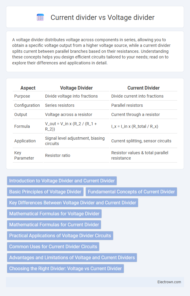
| Aspect | Voltage Divider | Current Divider |
|---|---|---|
| Purpose | Divide voltage into fractions | Divide current into fractions |
| Configuration | Series resistors | Parallel resistors |
| Output | Voltage across a resistor | Current through a resistor |
| Formula | V_out = V_in x (R_2 / (R_1 + R_2)) | I_x = I_in x (R_total / R_x) |
| Application | Signal level adjustment, biasing circuits | Current splitting, sensor circuits |
| Key Parameter | Resistor ratio | Resistor values & total parallel resistance |
Introduction to Voltage Divider and Current Divider
A voltage divider consists of resistors connected in series to produce a specific output voltage proportional to the input voltage, widely used for signal conditioning and voltage scaling. In contrast, a current divider features parallel resistors splitting the input current into desired portions for current regulation and distribution in circuits. Understanding these fundamental concepts is essential for designing effective electronic systems with controlled voltage and current levels.
Basic Principles of Voltage Divider
A voltage divider operates on the principle of distributing an input voltage across a series of resistors proportionally to their resistance values, enabling the extraction of a lower voltage output. The output voltage is calculated using the ratio of the resistance values, following the formula V_out = V_in * (R2 / (R1 + R2)) in a two-resistor system. This basic principle allows voltage dividers to be essential in signal conditioning, sensor interfacing, and reference voltage generation in electronic circuits.
Fundamental Concepts of Current Divider
The fundamental concept of a current divider involves distributing input current among parallel branches based on their resistive values, with the current inversely proportional to each branch's resistance according to Ohm's Law. Unlike voltage dividers, which rely on series resistors to proportionally split voltage, current dividers utilize parallel resistors to control and allocate the total current flowing through a circuit. This principle is essential for designing circuits where predictable current distribution is critical, such as in sensor networks and transistor biasing.
Key Differences Between Voltage Divider and Current Divider
Voltage dividers split input voltage into smaller output voltages based on resistor ratios, while current dividers distribute input current among parallel branches according to resistor values. Voltage dividers are used in series circuits to obtain specific voltage levels, whereas current dividers function in parallel circuits to control current flow through different paths. Your choice depends on whether you need to regulate voltage output or manage current distribution in the circuit.
Mathematical Formulas for Voltage Divider
Voltage divider circuits calculate output voltage using the formula V_out = V_in x (R2 / (R1 + R2)), where V_in is the input voltage, and R1 and R2 are the resistor values in series. This mathematical formula enables precise prediction of voltage drop across resistors, essential for designing circuits with specific voltage requirements. Understanding these formulas helps you optimize your circuit's voltage levels for efficient performance.
Mathematical Formulas for Current Divider
The mathematical formula for a current divider in parallel resistors is Ix = I_total * (R_total / Rx), where Ix is the current through resistor Rx, I_total is the total current entering the parallel network, and R_total is the equivalent resistance of the parallel combination. This formula is derived from Ohm's law and the property that voltage across parallel resistors is constant, allowing current to split inversely proportional to their resistances. Current division differs from voltage division, which uses the formula V_out = V_in * (R2 / (R1 + R2)) to find the voltage across a resistor in series.
Practical Applications of Voltage Divider Circuits
Voltage divider circuits are widely used in sensor interfacing to scale down high voltages to measurable levels for microcontrollers and analog-to-digital converters, ensuring accurate data acquisition. They play a crucial role in biasing transistors in amplifier circuits, providing stable voltage levels necessary for consistent device operation. Voltage dividers are also essential in adjusting signal levels in audio equipment and calibrating reference voltages in various electronic devices.
Common Uses for Current Divider Circuits
Current divider circuits are commonly used in electronics to distribute current among parallel branches, allowing precise control over current flow in each path. They are essential in sensor signal conditioning, biasing transistors, and protecting circuit components by limiting current to desired levels. Your designs benefit from current dividers when balancing loads or implementing efficient power management in complex circuits.
Advantages and Limitations of Voltage and Current Dividers
Voltage dividers offer precise voltage regulation with simple resistor networks, making them ideal for low-power applications but are limited by power dissipation and loading effects that can alter output voltage. Current dividers provide controlled current distribution through multiple parallel branches, useful in signal conditioning and measurement circuits, yet suffer from inaccuracies due to component tolerances and are ineffective for high-current loads. Both circuits require careful consideration of resistor values to optimize performance while minimizing energy loss and maintaining signal integrity.
Choosing the Right Divider: Voltage vs Current Divider
Choosing the right divider depends on whether you need to control voltage or current in your circuit. Voltage dividers are ideal for obtaining a specific voltage level from a higher voltage source using resistors in series, while current dividers distribute current through parallel resistors to manage current flow. Understanding your circuit's requirements ensures your voltage or current divider optimizes performance and protects your components effectively.
Voltage divider vs Current divider Infographic