Sample and hold circuits capture and maintain the input signal value at a specific moment, ensuring a stable output during processing, while track and hold circuits continuously follow the input signal and only hold its value when triggered. Understanding the differences between these two can significantly impact the accuracy of your analog-to-digital conversion, so explore the rest of the article to learn more about their applications and advantages.
Table of Comparison
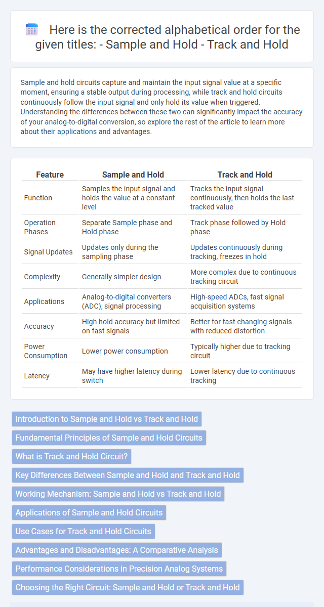
| Feature | Sample and Hold | Track and Hold |
|---|---|---|
| Function | Samples the input signal and holds the value at a constant level | Tracks the input signal continuously, then holds the last tracked value |
| Operation Phases | Separate Sample phase and Hold phase | Track phase followed by Hold phase |
| Signal Updates | Updates only during the sampling phase | Updates continuously during tracking, freezes in hold |
| Complexity | Generally simpler design | More complex due to continuous tracking circuit |
| Applications | Analog-to-digital converters (ADC), signal processing | High-speed ADCs, fast signal acquisition systems |
| Accuracy | High hold accuracy but limited on fast signals | Better for fast-changing signals with reduced distortion |
| Power Consumption | Lower power consumption | Typically higher due to tracking circuit |
| Latency | May have higher latency during switch | Lower latency due to continuous tracking |
Introduction to Sample and Hold vs Track and Hold
Sample and hold circuits capture and maintain a voltage level at a specific moment, ensuring stable analog-to-digital conversion. Track and hold circuits continuously track the input voltage before switching to hold mode, offering improved accuracy during rapid signal changes. The fundamental difference lies in the tracking capability, where track and hold circuits provide better performance for high-frequency or rapidly changing signals.
Fundamental Principles of Sample and Hold Circuits
Sample and hold circuits temporarily capture and maintain an analog signal's voltage for processing, using a switch and a holding capacitor to store the charge during the hold phase. The fundamental principle involves isolating the input signal during the hold period, preventing changes while the output is measured or digitized. Understanding this principle helps you design accurate analog-to-digital conversion systems with minimal signal distortion.
What is Track and Hold Circuit?
A Track and Hold circuit captures and maintains an analog voltage level for a specified period, enabling accurate analog-to-digital conversion. Unlike Sample and Hold circuits that briefly sample and freeze the voltage, Track and Hold continuously follows the input signal until the hold command is given, providing better performance in high-frequency applications. This functionality is critical in systems requiring precise timing and signal stability, such as data acquisition and digital oscilloscopes.
Key Differences Between Sample and Hold and Track and Hold
Sample and hold circuits capture and maintain a voltage level at a specific moment, pausing the signal for accurate analog-to-digital conversion, whereas track and hold circuits continuously follow the input signal until the hold phase begins. Key differences include the timing of signal acquisition and the design complexity, with track and hold typically offering faster response times and better accuracy in dynamic signal conditions. Your choice between them depends on the required precision and speed for applications in data acquisition and communication systems.
Working Mechanism: Sample and Hold vs Track and Hold
Sample and hold circuits capture and maintain a voltage level at a specific moment, freezing the signal during the hold phase for stable measurement or conversion. Track and hold circuits continuously follow the input signal during the tracking phase, updating the output in real-time, and then freeze the last value during the hold phase. Your choice between these mechanisms depends on the required precision and speed for signal processing applications.
Applications of Sample and Hold Circuits
Sample and hold circuits are widely used in analog-to-digital converters (ADCs) to capture and maintain a voltage level for precise digital conversion, ensuring accurate signal processing in communication systems and instrumentation. These circuits are essential in data acquisition systems, allowing your microcontroller or processor to read stable, instantaneous analog voltage values without signal distortion. Their applications extend to medical devices, radar systems, and digital oscilloscopes where precise timing and signal integrity are crucial.
Use Cases for Track and Hold Circuits
Track and hold circuits excel in high-speed data acquisition systems where rapid signal sampling and stable output voltage are critical, such as analog-to-digital converters (ADCs) in communication devices. These circuits maintain signal integrity during transient changes, making them ideal for radar systems and precise measurement instruments. Their ability to follow rapidly changing inputs before holding the value ensures accurate digitization of dynamic signals in real-time applications.
Advantages and Disadvantages: A Comparative Analysis
Sample and hold circuits excel in simplicity and lower power consumption, making them ideal for basic analog-to-digital conversion where precision is less critical. Track and hold circuits offer superior accuracy and faster response by continuously following the input signal before capturing it, though they are more complex and consume more power. Your choice depends on the application's need for speed, accuracy, and power efficiency, balancing the straightforward design of sample and hold against the high fidelity of track and hold systems.
Performance Considerations in Precision Analog Systems
Sample and hold circuits provide stable, accurate signal retention by capturing and holding the input voltage, minimizing errors crucial for precision analog systems. Track and hold circuits allow continuous input tracking before holding, offering faster response but with potential trade-offs in noise and linearity performance. Selecting between sample and hold versus track and hold impacts key parameters like acquisition time, distortion, and signal integrity in high-precision data acquisition and measurement applications.
Choosing the Right Circuit: Sample and Hold or Track and Hold
Choosing between sample and hold and track and hold circuits depends on the required signal fidelity and application speed. Sample and hold circuits capture and maintain the input voltage at a specific instant, ideal for analog-to-digital converters needing stable signals during conversion. Track and hold circuits continuously follow the input signal and freeze it at the hold command, offering better performance in high-frequency applications where signal variations during sampling are critical.
Sample and hold vs track and hold Infographic