Wired-AND and wired-OR are fundamental digital logic techniques used to combine multiple signals at the hardware level, with wired-AND typically implemented using open-drain or open-collector outputs that pull the line low when active, while wired-OR uses pull-up resistors to pull the line high. Understanding these concepts can help you optimize your circuit designs for reliability and efficiency, so continue reading to explore their differences and applications.
Table of Comparison
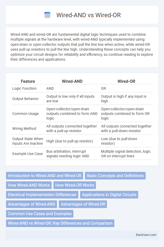
| Feature | Wired-AND | Wired-OR |
|---|---|---|
| Logic Function | AND | OR |
| Output Behavior | Output is low only if all inputs are low | Output is high if any input is high |
| Common Usage | Open-collector/open-drain outputs combined to form AND logic | Open-collector/open-drain outputs combined to form OR logic |
| Wiring Method | All outputs connected together with a pull-up resistor | All outputs connected together with a pull-down resistor |
| Output State When Inputs Are Inactive | High (due to pull-up resistor) | Low (due to pull-down resistor) |
| Example Use Case | Bus arbitration, interrupt signals needing logic AND | Multiple signal detection, logic OR on interrupt lines |
Introduction to Wired-AND and Wired-OR
Wired-AND and Wired-OR are fundamental logic combining techniques used in digital circuits to implement boolean operations without extra gates. Wired-AND connects outputs together so that the resulting signal is the logical AND of individual signals, while Wired-OR similarly combines outputs to produce a logical OR function. Understanding these methods helps optimize circuit design by reducing complexity and improving signal integration in your digital systems.
Basic Concepts and Definitions
Wired-AND and wired-OR are digital logic techniques used to combine multiple signal lines directly without extra gates. Wired-AND connects outputs to a common line where all signals must be active low for the line to be low, effectively performing a logical AND operation. Wired-OR uses open-drain or open-collector outputs connected to a common line pulled high, resulting in a low signal only when all inputs are low, thus functioning as a logical OR.
How Wired-AND Works
Wired-AND logic works by connecting multiple open-drain or open-collector outputs to a single line, where the line is pulled low if any of the connected devices output a low signal, effectively performing an AND function. This configuration relies on external pull-up resistors to maintain a high state only when all devices release the line, enabling multiple devices to share the bus without direct electrical conflicts. Wired-AND reduces the need for additional gates, simplifying hardware design in digital circuits such as I2C communication or multi-master bus systems.
How Wired-OR Works
Wired-OR logic uses open-collector or open-drain outputs interconnected on a common wire, where any output pulling the line low results in a low signal, effectively implementing a logical OR function. This structure ensures that the line is high only when all connected outputs are inactive, allowing multiple devices to share the line without conflict. You can simplify complex digital circuits by using wired-OR configurations, especially in bus systems or interrupt lines.
Electrical Implementation Differences
Wired-AND and wired-OR circuits differ primarily in their electrical implementation: wired-AND typically uses open-drain or open-collector outputs that pull the line low to represent a logical "0," requiring an external pull-up resistor to achieve a high state. Wired-OR circuits often employ open-source or open-emitter configurations, where devices pull the line high to indicate a logical "1," while a pull-down resistor ensures the line is low when inactive. The choice of transistor type and resistor placement in the circuit directly affects the signal integrity, power consumption, and compatibility with specific logic families like TTL or CMOS.
Applications in Digital Circuits
Wired-AND and wired-OR configurations are commonly used in digital logic circuits for implementing specific logic functions without additional gates. Wired-AND is often applied in open-collector or open-drain outputs to create a multi-input AND function by directly connecting outputs, making it ideal for bus arbitration and interrupt lines. Wired-OR circuits find use in systems requiring a logical OR function with minimal components, such as priority encoders and multi-level enable signals.
Advantages of Wired-AND
Wired-AND logic offers enhanced noise immunity by requiring all inputs to be low for the output to go low, ensuring more stable and reliable signal detection in complex digital circuits. It simplifies the design of fault-tolerant systems by automatically providing a logical AND function without the need for additional gates, reducing component count and power consumption. This logic style is particularly advantageous in wired logic configurations such as open-drain or open-collector networks where multiple outputs can be safely connected to form a combined output.
Advantages of Wired-OR
Wired-OR logic offers simplicity in digital circuit design by allowing multiple outputs to be connected directly to a shared line, reducing the number of required components and saving board space. It enhances fault tolerance since any high signal from connected devices will result in a high output, improving reliability in multi-source signaling environments. Your circuits benefit from lower power consumption and easier implementation in wired communication protocols such as open-drain or open-collector configurations.
Common Use Cases and Examples
Wired-AND connections are commonly used in open-collector or open-drain outputs where multiple devices share a bus and must pull the line low to signal active states, such as I2C communication lines or interrupt lines in microcontroller systems. Wired-OR configurations are typically found in transistor-transistor logic (TTL) circuits where multiple outputs are connected to a single line, allowing any active high signal to be detected, seen in priority encoders or alarm systems combining multiple inputs. These wiring methods enable simple hardware logic functions without additional gates, optimizing circuit design for conditions requiring collective input monitoring or control.
Wired-AND vs Wired-OR: Key Differences and Comparison
Wired-AND and Wired-OR are fundamental logic configurations used in digital circuits for combining multiple signals. Wired-AND is achieved by connecting open-drain or open-collector outputs in parallel, resulting in a logical AND function where the output is low only if all inputs are low. Wired-OR, conversely, also uses open-drain or open-collector outputs but produces a logical OR function, outputting high if at least one input is high, making these configurations essential for bus systems, interrupt handling, and signal gating in microcontroller and FPGA designs.
Wired-AND vs wired-OR Infographic