Coplanar waveguides offer improved isolation and reduced radiation losses compared to microstrip lines, making them ideal for high-frequency applications requiring better signal integrity. Explore the detailed comparison to understand which transmission line best suits your RF design needs.
Table of Comparison
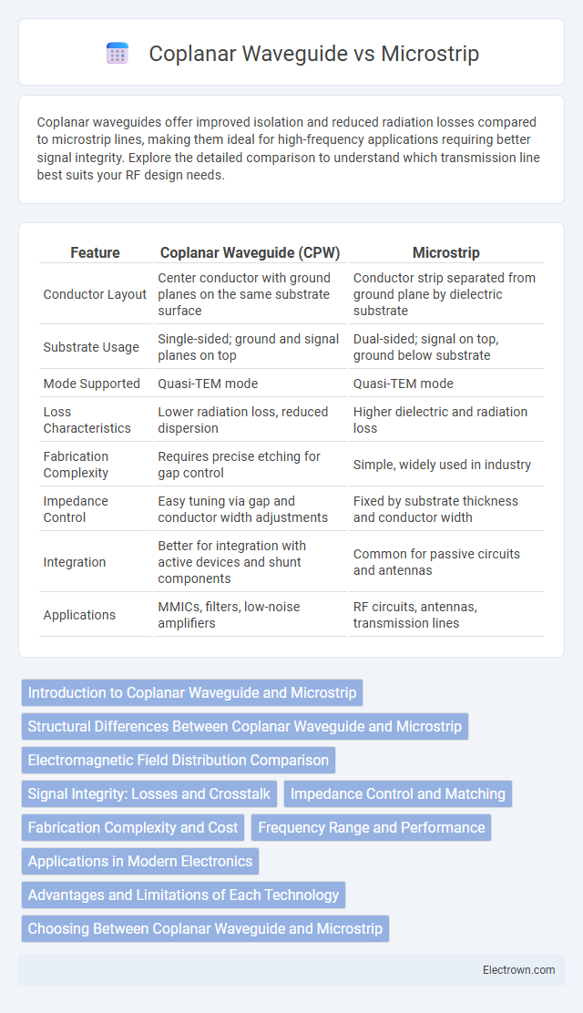
| Feature | Coplanar Waveguide (CPW) | Microstrip |
|---|---|---|
| Conductor Layout | Center conductor with ground planes on the same substrate surface | Conductor strip separated from ground plane by dielectric substrate |
| Substrate Usage | Single-sided; ground and signal planes on top | Dual-sided; signal on top, ground below substrate |
| Mode Supported | Quasi-TEM mode | Quasi-TEM mode |
| Loss Characteristics | Lower radiation loss, reduced dispersion | Higher dielectric and radiation loss |
| Fabrication Complexity | Requires precise etching for gap control | Simple, widely used in industry |
| Impedance Control | Easy tuning via gap and conductor width adjustments | Fixed by substrate thickness and conductor width |
| Integration | Better for integration with active devices and shunt components | Common for passive circuits and antennas |
| Applications | MMICs, filters, low-noise amplifiers | RF circuits, antennas, transmission lines |
Introduction to Coplanar Waveguide and Microstrip
Coplanar waveguide (CPW) and microstrip are two popular transmission line structures used in high-frequency circuit design. CPW features a central conductor flanked by two ground planes on the same substrate surface, offering low radiation losses and easy shunt and series component integration, which makes it ideal for microwave and millimeter-wave applications. Microstrip consists of a single conductor separated from a ground plane by a dielectric substrate, providing a simple fabrication process and wide bandwidth performance that suits many RF and microwave circuits; understanding these differences helps optimize your design for specific application requirements.
Structural Differences Between Coplanar Waveguide and Microstrip
Coplanar waveguides feature a central conductor flanked by two ground planes on the same substrate surface, enabling easier integration with surface-mounted components and reduced radiation loss. Microstrip lines consist of a conducting strip separated from a ground plane by a dielectric substrate, which offers simpler fabrication but higher radiation and dispersion effects. Understanding these structural differences helps optimize your high-frequency circuit design for performance, manufacturability, and size constraints.
Electromagnetic Field Distribution Comparison
Coplanar waveguides (CPWs) feature electromagnetic fields concentrated between the central conductor and adjacent ground planes on the same substrate surface, enabling reduced radiation loss and enhanced signal integrity. Microstrip lines exhibit electromagnetic fields primarily confined between the conductor and the ground plane on the opposite substrate side, which can lead to increased dielectric losses and substrate coupling. Understanding this field distribution difference is crucial for optimizing your RF circuit design and improving overall electromagnetic compatibility.
Signal Integrity: Losses and Crosstalk
Coplanar waveguides exhibit lower crosstalk and reduced signal losses compared to microstrip lines, owing to their symmetric ground planes that provide superior electromagnetic shielding. Microstrip designs often suffer from higher dielectric losses and increased radiation, which can degrade signal integrity over longer distances. Understanding these differences is crucial for optimizing Your high-frequency PCB layouts to maintain minimal signal degradation and enhanced performance.
Impedance Control and Matching
Coplanar waveguide offers superior impedance control through its symmetric structure, facilitating easier matching with other planar devices and reducing parasitic effects. Microstrip lines rely heavily on substrate thickness and dielectric constant for impedance determination, making precise matching more challenging in varying environments. Your choice impacts signal integrity, with coplanar waveguides providing enhanced consistency for high-frequency impedance matching applications.
Fabrication Complexity and Cost
Coplanar waveguides (CPW) offer simpler fabrication processes than microstrip lines due to their planar structure and single-layer metallization, which reduces alignment challenges and overall manufacturing steps. Microstrip lines require multilayer fabrication and precise dielectric thickness control, increasing production complexity and associated costs. Consequently, CPWs often present a cost-effective alternative in high-frequency circuit design, particularly for prototypes and low-volume production.
Frequency Range and Performance
Coplanar waveguides (CPW) offer superior performance at high frequencies, typically from GHz to millimeter-wave ranges, due to their lower dispersion and reduced radiation loss compared to microstrip lines. Microstrip lines operate effectively from MHz to several GHz but face increased dielectric and conductor losses at higher frequencies, limiting their performance in ultra-high frequency applications. Your choice between CPW and microstrip will depend on the targeted frequency range and the need for minimal signal degradation in your design.
Applications in Modern Electronics
Coplanar waveguide (CPW) is widely used in high-frequency circuits for its ease of integration with active components and superior suppression of parasitic modes, making it ideal in RF and microwave applications such as filters, antennas, and sensors. Microstrip technology remains prevalent in printed circuit boards (PCBs) due to its simplicity, low cost, and compatibility with mass production, commonly found in communication devices, satellite systems, and radar equipment. Both transmission lines are critical in modern electronics, with CPW favored for precision RF design and microstrip preferred for general-purpose signal routing and cost-effective manufacturing.
Advantages and Limitations of Each Technology
Coplanar waveguides (CPW) offer advantages such as ease of integration with active devices and reduced radiation loss due to their planar geometry with ground planes on the same layer, enhancing signal integrity at microwave frequencies. Microstrip lines provide simplicity in fabrication and are compatible with multilayer PCB processes, making them cost-effective for a wide range of RF and microwave circuits, though they exhibit higher radiation losses and dispersion compared to CPW. While CPW supports tighter coupling and wider bandwidth, its complex impedance control can pose design challenges; microstrip technology, despite its limitations in isolation and dispersion, remains preferred for standard applications due to its versatility and established design methodologies.
Choosing Between Coplanar Waveguide and Microstrip
Choosing between coplanar waveguide and microstrip depends on your circuit requirements such as signal integrity, power handling, and fabrication constraints. Coplanar waveguides offer lower radiation loss and improved isolation, making them ideal for high-frequency, high-power applications with tight integration needs. Microstrip lines provide simpler fabrication and cost advantages, preferred for standard PCB layouts and moderate frequency designs.
Coplanar Waveguide vs Microstrip Infographic