Directional couplers efficiently split or combine signals with minimal loss, enabling precise measurement or signal routing in RF systems, while isolators protect sensitive components by allowing signal flow in one direction and preventing reflections. Understanding the differences between these devices can optimize your system's performance--read on to explore their unique applications and benefits.
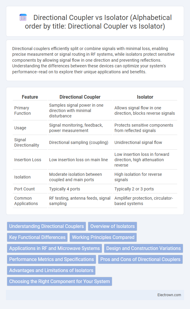
Table of Comparison
| Feature | Directional Coupler | Isolator |
|---|---|---|
| Primary Function | Samples signal power in one direction with minimal disturbance | Allows signal flow in one direction, blocks reverse signals |
| Usage | Signal monitoring, feedback, power measurement | Protects sensitive components from reflected signals |
| Signal Directionality | Directional sampling (coupling) | Unidirectional signal flow |
| Insertion Loss | Low insertion loss on main line | Low insertion loss in forward direction, high attenuation reverse |
| Isolation | Moderate isolation between coupled and main ports | High isolation for reverse signals |
| Port Count | Typically 4 ports | Typically 2 or 3 ports |
| Common Applications | RF testing, antenna feeds, signal sampling | Amplifier protection, circulator-based systems |
Understanding Directional Couplers
Directional couplers are passive devices used in RF and microwave systems to sample a signal without disturbing the main power flow, enabling signal monitoring and measurement. Their key feature is the ability to couple a specific portion of the input signal to an output port while isolating the rest of the power, which distinguishes them from isolators designed primarily to prevent signal reflection. Understanding directional couplers helps you optimize signal routing and measurement accuracy in communication or radar systems.
Overview of Isolators
Isolators are non-reciprocal devices designed to allow signal flow in one direction while preventing reflections or interference from traveling back toward the source. They protect sensitive components like amplifiers and lasers from damaging reflected power, ensuring stable and reliable system performance. Your communication or measurement system benefits from isolators by maintaining signal integrity and reducing noise caused by unwanted feedback.
Key Functional Differences
A directional coupler splits signal power between output ports with minimal interference, enabling signal sampling and monitoring without disrupting the main transmission path. An isolator permits signal flow in one direction while blocking reverse signals to protect sensitive components from feedback or reflections. Your choice depends on whether you need bidirectional signal sampling or unidirectional isolation for equipment protection.
Working Principles Compared
A directional coupler operates by splitting input signal power into two output ports in specific directions, enabling signal sampling and monitoring without disturbing the main transmission line. An isolator, on the other hand, uses non-reciprocal components like ferrite materials to allow signal flow in one direction while preventing reflections and interference in the reverse path. Understanding the working principles helps you select the right device for applications requiring signal routing versus protection from backflow.
Applications in RF and Microwave Systems
Directional couplers are crucial for signal sampling, monitoring, and injection in RF and microwave systems, enabling precise measurement and control without interrupting the main transmission path. Isolators protect sensitive components from reflected power and improve system stability by allowing signal flow in only one direction, essential in preventing damage to amplifiers and oscillators. Both components enhance performance in communication systems, radar, and test setups, but their distinct functions serve complementary roles in managing signal integrity and power flow.
Design and Construction Variations
Directional couplers typically consist of two coupled transmission lines or waveguides designed to split or sample signals with high directivity, using either lumped elements or distributed structures such as microstrip or stripline. Isolators are based on non-reciprocal components like ferrite materials combined with magnets, employing Faraday rotation to allow signal flow in one direction while absorbing or reflecting signals in the opposite direction. The fundamental design difference lies in the linear, reciprocal coupling mechanism of directional couplers versus the non-reciprocal, magnetically biased ferrite construction of isolators, influencing their respective applications in RF and microwave circuits.
Performance Metrics and Specifications
Directional couplers and isolators differ significantly in performance metrics such as insertion loss, isolation, and directivity. Directional couplers are characterized by coupling factor, directivity typically above 20 dB, and flat frequency response, while isolators emphasize high isolation--often exceeding 20 dB--to protect sensitive components from reflected signals and maintain low insertion loss around 0.5 dB. Your choice depends on whether signal sampling with minimal disturbance (directional coupler) or signal flow protection with minimal reverse power (isolator) is required.
Pros and Cons of Directional Couplers
Directional couplers offer precise signal sampling with minimal insertion loss and excellent directivity, making them ideal for monitoring and signal routing in RF systems. However, they tend to have limited isolation between ports and can introduce signal distortion at high power levels, which may affect system performance. Your choice depends on whether accurate signal measurement or preventing signal reflection is more critical for your application.
Advantages and Limitations of Isolators
Isolators provide unidirectional signal flow, preventing reflected signals from damaging sensitive components, which enhances system stability and protects RF circuits. Their limitation lies in insertion loss, which can slightly reduce signal strength and impact overall system efficiency. Isolators are less effective at handling high power levels compared to some directional couplers, making power handling capacity a crucial selection criterion.
Choosing the Right Component for Your System
Selecting between a directional coupler and an isolator depends on your system's specific needs for signal flow control and reflection management. Directional couplers provide precise signal sampling without interrupting transmission, ideal for monitoring and measurement applications, while isolators protect components by preventing undesired signal reflections that can cause damage or interference. Understanding your system's requirements for isolation, insertion loss, and power handling ensures you choose the component that optimizes performance and reliability.
Directional Coupler vs Isolator Infographic