Mismatch loss occurs when there is an impedance difference between connected components, causing signal reflections and reduced power transfer, while insertion loss refers to the signal power loss caused by introducing a device or component into a transmission line. Understanding the distinctions between mismatch loss and insertion loss is essential for optimizing Your communication system's efficiency, so explore the rest of the article for detailed insights.
Table of Comparison
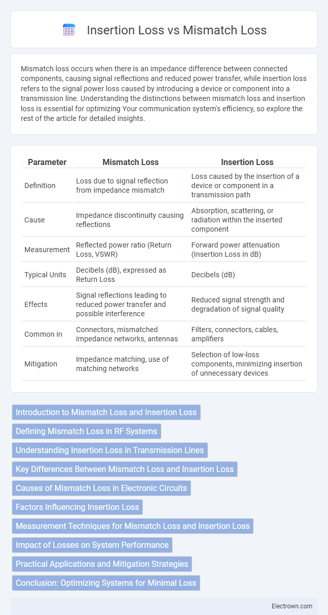
| Parameter | Mismatch Loss | Insertion Loss |
|---|---|---|
| Definition | Loss due to signal reflection from impedance mismatch | Loss caused by the insertion of a device or component in a transmission path |
| Cause | Impedance discontinuity causing reflections | Absorption, scattering, or radiation within the inserted component |
| Measurement | Reflected power ratio (Return Loss, VSWR) | Forward power attenuation (Insertion Loss in dB) |
| Typical Units | Decibels (dB), expressed as Return Loss | Decibels (dB) |
| Effects | Signal reflections leading to reduced power transfer and possible interference | Reduced signal strength and degradation of signal quality |
| Common in | Connectors, mismatched impedance networks, antennas | Filters, connectors, cables, amplifiers |
| Mitigation | Impedance matching, use of matching networks | Selection of low-loss components, minimizing insertion of unnecessary devices |
Introduction to Mismatch Loss and Insertion Loss
Mismatch loss occurs when there is an impedance difference between connected components in a transmission line, causing signal reflections and power loss. Insertion loss refers to the reduction in signal power resulting from inserting a device or component into a transmission path, measured in decibels (dB). Understanding both mismatch loss and insertion loss is crucial for optimizing your network's signal integrity and overall performance.
Defining Mismatch Loss in RF Systems
Mismatch loss in RF systems occurs when the impedance of a load does not perfectly match the source impedance, causing a portion of the signal to be reflected back toward the source rather than transmitted forward. This reflection leads to reduced power transfer efficiency and signal degradation, negatively impacting system performance. Understanding mismatch loss helps you optimize impedance matching to minimize reflections and enhance overall RF system reliability.
Understanding Insertion Loss in Transmission Lines
Insertion loss in transmission lines refers to the reduction in signal power caused by the insertion of a device or component, expressed in decibels (dB). It occurs due to factors such as impedance mismatches, conductor resistance, dielectric losses, and connector interfaces, which collectively degrade signal integrity. Understanding insertion loss is essential for optimizing transmission line performance and ensuring efficient signal transfer in high-frequency communication systems.
Key Differences Between Mismatch Loss and Insertion Loss
Mismatch loss occurs due to impedance differences at the connection points in a transmission line, resulting in signal reflections and reduced power transfer efficiency. Insertion loss represents the total signal power loss when a device or component is inserted into the transmission line, encompassing absorption, scattering, and reflection losses. While mismatch loss is specifically caused by impedance discontinuities, insertion loss accounts for all forms of power attenuation introduced by the inserted component.
Causes of Mismatch Loss in Electronic Circuits
Mismatch loss in electronic circuits primarily arises from impedance disparities between interconnected components, causing signal reflections and power dissipation. Factors contributing to these impedance mismatches include manufacturing tolerances, temperature variations, and parasitic elements such as stray capacitance and inductance. These mismatches reduce the efficiency of power transfer, increasing signal attenuation compared to insertion loss, which mainly results from intrinsic material and connector resistances.
Factors Influencing Insertion Loss
Insertion loss is influenced by factors such as connector quality, fiber alignment, and the cleanliness of optical interfaces, which directly affect signal attenuation in fiber optic systems. Core diameter mismatch and macrobending of the fiber can also increase insertion loss by inducing additional signal scattering and absorption. Environmental conditions like temperature fluctuations and mechanical stress contribute to variations in insertion loss by altering the physical properties of the fiber and connectors.
Measurement Techniques for Mismatch Loss and Insertion Loss
Mismatch loss measurement typically involves using a network analyzer to determine the voltage standing wave ratio (VSWR) or return loss at the interface, enabling precise quantification of signal reflection caused by impedance discontinuities. Insertion loss measurement employs a spectrum analyzer or power meter in conjunction with a signal source to measure the power reduction through a device or transmission line, indicating the overall attenuation introduced. Both techniques rely on calibrated test setups and reference measurements to ensure accuracy in assessing the performance of RF and optical components.
Impact of Losses on System Performance
Mismatch loss causes signal reflection at impedance discontinuities, reducing power transfer efficiency and potentially causing signal distortion in your system. Insertion loss results from the introduction of components like connectors or cables, decreasing signal strength and overall system sensitivity. Both losses degrade system performance by lowering signal-to-noise ratio and increasing error rates, emphasizing the need for careful component selection and impedance matching.
Practical Applications and Mitigation Strategies
Mismatch loss occurs primarily in RF and microwave systems due to impedance discontinuities, causing signal reflections and reduced power transfer efficiency; insertion loss, meanwhile, arises from energy dissipation within components such as cables, connectors, and filters, directly impacting signal strength. Practical applications in optical fiber communications emphasize minimizing insertion loss to maintain signal integrity over long distances, while in antenna design, mitigating mismatch loss enhances return loss and overall system performance. Mitigation strategies include using impedance matching networks like quarter-wave transformers to reduce mismatch loss, and selecting low-loss materials or optimizing connector quality to decrease insertion loss in transmission lines.
Conclusion: Optimizing Systems for Minimal Loss
Mismatch loss results from impedance differences causing signal reflections, while insertion loss occurs due to the inherent resistance and attenuation in system components. Minimizing both losses is crucial for maximizing signal integrity and overall system efficiency in high-frequency and fiber optic networks. By carefully selecting compatible connectors, maintaining proper impedance matching, and using high-quality components, you ensure your system operates with minimal total loss.
Mismatch Loss vs Insertion Loss Infographic