Class E amplifiers provide high efficiency by switching devices on and off with minimal overlap between voltage and current, ideal for RF power applications where power loss reduction is critical. Exploring the differences between Class E and Class F amplifiers will help you understand which technology better suits your specific amplifier design needs. Read on to learn more.
Table of Comparison
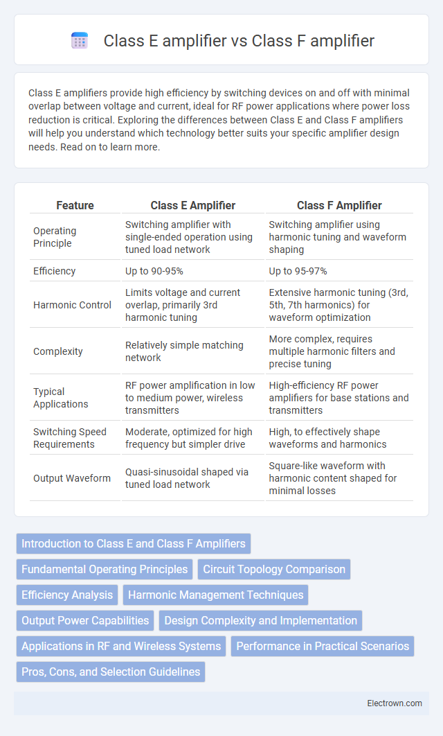
| Feature | Class E Amplifier | Class F Amplifier |
|---|---|---|
| Operating Principle | Switching amplifier with single-ended operation using tuned load network | Switching amplifier using harmonic tuning and waveform shaping |
| Efficiency | Up to 90-95% | Up to 95-97% |
| Harmonic Control | Limits voltage and current overlap, primarily 3rd harmonic tuning | Extensive harmonic tuning (3rd, 5th, 7th harmonics) for waveform optimization |
| Complexity | Relatively simple matching network | More complex, requires multiple harmonic filters and precise tuning |
| Typical Applications | RF power amplification in low to medium power, wireless transmitters | High-efficiency RF power amplifiers for base stations and transmitters |
| Switching Speed Requirements | Moderate, optimized for high frequency but simpler drive | High, to effectively shape waveforms and harmonics |
| Output Waveform | Quasi-sinusoidal shaped via tuned load network | Square-like waveform with harmonic content shaped for minimal losses |
Introduction to Class E and Class F Amplifiers
Class E amplifiers utilize a single-ended switching topology designed for high efficiency at radio frequencies by minimizing switching losses through zero-voltage switching. Class F amplifiers enhance efficiency further by employing harmonic tuning with multiple resonant circuits to shape voltage and current waveforms, significantly reducing overlap and power dissipation. Understanding these amplifier classes helps optimize Your design choices for power efficiency and linearity in high-frequency applications.
Fundamental Operating Principles
Class E amplifiers operate by switching the transistor on and off at high frequencies, utilizing a resonant circuit to shape voltage and current waveforms, minimizing overlap and power loss. Class F amplifiers employ harmonic tuning using multiple resonators to shape voltage and current waveforms, boosting efficiency by reducing power dissipation during switching. Understanding these fundamental operating principles helps you choose the right amplifier for high-efficiency RF applications.
Circuit Topology Comparison
Class E amplifiers utilize a highly efficient switching mode topology with a single MOSFET transistor operating as a switch, characterized by a simple LC tuning network for shaping voltage and current waveforms to minimize power dissipation. In contrast, Class F amplifiers employ harmonic tuning through multiple resonant circuits that shape the voltage and current waveforms using Fourier series, enhancing efficiency by controlling higher order harmonics. The Class E circuit's simplicity results in ease of implementation and lower component count, while Class F circuits achieve greater efficiency by precisely controlling harmonic content but require complex filter networks and precise component matching.
Efficiency Analysis
Class E amplifiers achieve high efficiency by utilizing a switch-mode design with a resonant circuit that minimizes overlap between voltage and current waveforms, often reaching efficiencies above 85%. Class F amplifiers enhance efficiency through harmonic tuning, shaping voltage and current waveforms to reduce power dissipation and can exceed 90% efficiency under optimal conditions. Your choice between Class E and Class F amplifiers should consider specific frequency ranges and load conditions to maximize overall power efficiency.
Harmonic Management Techniques
Class E amplifiers employ a single-ended switching operation with a tuned load network that minimizes harmonic content by shaping voltage and current waveforms to reduce overlap, effectively controlling switching losses. Class F amplifiers utilize harmonic-tuned resonators to create specific harmonic voltage waveforms, ideally a square wave, enhancing efficiency by recycling energy from harmonics and improving the fundamental output. Harmonic management in Class F is more complex but achieves higher efficiency through precise waveform engineering, while Class E focuses on simplified harmonic suppression with optimized switching transitions.
Output Power Capabilities
Class E amplifiers deliver high efficiency with moderate output power, typically suited for applications requiring low to medium power levels due to switching losses and harmonic suppression techniques. Class F amplifiers achieve significantly higher output power capabilities by utilizing harmonic tuning and waveform engineering, leading to improved power efficiency and reduced distortion at higher power levels. Your choice between Class E and Class F amplifiers depends on the desired balance between output power capacity and efficiency for specific RF applications.
Design Complexity and Implementation
Class E amplifiers feature simpler design structures with a single MOSFET switch and a tuned load network, making them easier to implement for high-efficiency RF applications. In contrast, Class F amplifiers require more complex harmonic tuning circuits and multiple frequency-selective components to achieve waveform shaping, increasing design intricacy and implementation challenges. Your choice between these amplifiers depends on balancing design complexity against efficiency and performance requirements.
Applications in RF and Wireless Systems
Class E amplifiers are widely used in RF and wireless systems for their high efficiency and ability to operate at high frequencies, making them ideal for power amplification in transmitters. Class F amplifiers leverage harmonic tuning to enhance efficiency and output power, commonly applied in advanced communication systems requiring linearity and spectral efficiency. Your choice depends on balancing efficiency, linearity, and frequency requirements specific to the RF application.
Performance in Practical Scenarios
Class E amplifiers excel in high-efficiency applications with simpler designs and are ideal for RF transmitters operating at fixed frequencies, delivering low power loss and reduced heat dissipation. Class F amplifiers achieve higher efficiency through harmonic tuning, making them suitable for high-frequency, high-power scenarios where waveform shaping improves performance but involves more complex circuitry. Understanding your application's frequency, power requirements, and complexity will determine whether a Class E or Class F amplifier offers the optimal performance in practical scenarios.
Pros, Cons, and Selection Guidelines
Class E amplifiers offer high efficiency, typically above 80%, making them ideal for RF applications requiring low power consumption and minimal heat dissipation. However, their operation relies on precise tuning of components, which complicates design and can limit bandwidth. Class F amplifiers achieve even higher efficiency by employing harmonic tuning to shape voltage and current waveforms, but they demand complex circuit implementation and may suffer from stability issues, so selection should consider power requirements, frequency range, and design complexity.
Class E amplifier vs class F amplifier Infographic