Analog voltage meters measure electrical potential difference across two points, providing insights into voltage levels in a circuit, while analog current meters gauge the flow of electric charge, reflecting the current passing through a component. Understanding the distinctions between these instruments can help you select the right tool for accurate electrical measurements; read on to explore their functions, applications, and advantages.
Table of Comparison
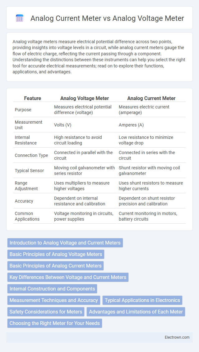
| Feature | Analog Voltage Meter | Analog Current Meter |
|---|---|---|
| Purpose | Measures electrical potential difference (voltage) | Measures electric current (amperage) |
| Measurement Unit | Volts (V) | Amperes (A) |
| Internal Resistance | High resistance to avoid circuit loading | Low resistance to minimize voltage drop |
| Connection Type | Connected in parallel with the circuit | Connected in series with the circuit |
| Typical Sensor | Moving coil galvanometer with series resistor | Shunt resistor with moving coil galvanometer |
| Range Adjustment | Uses multipliers to measure higher voltages | Uses shunt resistors to measure higher currents |
| Accuracy | Dependent on internal resistance and calibration | Dependent on shunt resistor precision and calibration |
| Common Applications | Voltage monitoring in circuits, power supplies | Current monitoring in motors, battery circuits |
Introduction to Analog Voltage and Current Meters
Analog voltage meters measure electric potential difference in volts using a moving needle over a calibrated scale, providing precise voltage readings in circuits. Analog current meters, or ammeters, gauge electric current in amperes by detecting the flow of electric charge through a coil, offering real-time current levels. Both instruments rely on electromagnetic deflection mechanisms but are specifically designed and calibrated for voltage or current measurement, ensuring accurate and reliable performance in electrical diagnostics.
Basic Principles of Analog Voltage Meters
Analog voltage meters operate based on the deflection of a needle caused by the voltage-induced current passing through a sensitive coil within a magnetic field, typically using a galvanometer mechanism. They measure potential difference by allowing a small current to flow proportional to the voltage across the meter's input terminals, often incorporating a high internal resistance to minimize circuit loading. Understanding these basic principles helps you select the right analog meter for accurate voltage measurements in various electrical applications.
Basic Principles of Analog Current Meters
Analog current meters operate based on the deflection of a needle caused by the magnetic force generated when electric current flows through a coil. The coil, suspended in a magnetic field, moves proportionally to the current, allowing you to measure the electrical current accurately. Unlike analog voltage meters that measure potential difference, analog current meters are designed to provide precise current readings by converting electrical flow into mechanical movement.
Key Differences Between Voltage and Current Meters
Analog voltage meters measure electrical potential difference in volts by connecting in parallel with the circuit, whereas analog current meters measure electric current in amperes by connecting in series. Voltage meters have high internal resistance to minimize circuit impact, while current meters have low internal resistance to allow accurate current flow measurement. The distinct connection methods and resistance values are critical for their correct application and performance in electrical diagnostics.
Internal Construction and Components
Analog voltage meters typically feature high-resistance internal components, including a sensitive moving coil galvanometer and a series resistor to limit current flow, ensuring accurate voltage measurement without significantly loading the circuit. In contrast, analog current meters incorporate a low-resistance shunt resistor connected in series with the coil to safely measure current by producing a proportional voltage drop. Understanding these construction differences allows you to select the appropriate meter for precise monitoring of electrical parameters in your applications.
Measurement Techniques and Accuracy
Analog voltage meters measure potential difference by detecting the deflection of a needle proportional to voltage applied across their terminals, typically using a high internal resistance to minimize circuit loading. Analog current meters, or ammeters, measure current by detecting the magnetic field generated by current flow through a low-resistance shunt, providing a direct correlation between needle deflection and current magnitude. Accuracy in voltage meters depends on high input impedance and stable calibration, whereas analog current meters require precise shunt resistors and minimal burden voltage to maintain measurement fidelity.
Typical Applications in Electronics
Analog voltage meters are typically used in electronics to measure voltage levels in circuits, allowing you to monitor power supply outputs, battery voltage, and signal voltages with precision. Analog current meters, on the other hand, are essential for assessing current flow in components like resistors, motors, and electronic devices, ensuring circuits function within safe operating limits. Both meters provide real-time, intuitive readings crucial for troubleshooting and maintaining electronic systems.
Safety Considerations for Meters
Analog voltage meters require high input resistance to minimize circuit loading and prevent damage, ensuring safe measurements in high-voltage environments. Analog current meters must be connected in series and have low internal resistance to avoid excessive voltage drop and overheating risks, demanding careful handling to prevent short circuits. Your safety depends on selecting the appropriate meter type and adhering to proper connection procedures based on the measured parameter.
Advantages and Limitations of Each Meter
Analog voltage meters offer precise voltage measurement with minimal circuit interference and simple design, making them ideal for high-impedance applications, yet they may suffer from lower accuracy in fluctuating loads. Analog current meters provide direct current measurement through galvanometer deflection, offering real-time monitoring in low-resistance circuits, but they can introduce additional resistance and potential signal distortion. Both meters rely on mechanical needle movement, which can be susceptible to vibration and require careful calibration to maintain measurement accuracy.
Choosing the Right Meter for Your Needs
Choosing the right meter for your needs depends on whether you are measuring voltage or current, as analog voltage meters are designed to detect potential difference across components, while analog current meters measure the flow of electric charge through a circuit. Voltage meters usually have high input impedance to avoid circuit interference, whereas current meters require low internal resistance to accurately reflect current without altering the circuit. Understanding the specific parameter you need to measure ensures accurate readings and protects your equipment from damage.
analog voltage meter vs analog current meter Infographic