An RC integrator uses a resistor and capacitor to smooth signals, ideal for low-frequency applications, while an LC integrator employs inductors and capacitors, suitable for higher frequency ranges due to lower signal loss and better phase characteristics. Explore the detailed differences to understand which integrator fits Your electronic project needs.
Table of Comparison
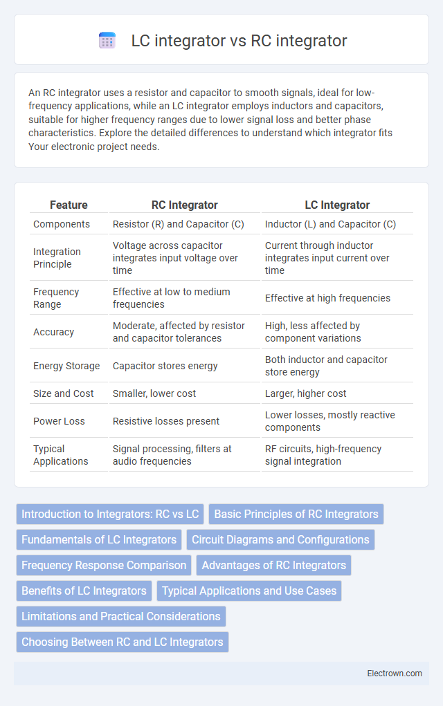
| Feature | RC Integrator | LC Integrator |
|---|---|---|
| Components | Resistor (R) and Capacitor (C) | Inductor (L) and Capacitor (C) |
| Integration Principle | Voltage across capacitor integrates input voltage over time | Current through inductor integrates input current over time |
| Frequency Range | Effective at low to medium frequencies | Effective at high frequencies |
| Accuracy | Moderate, affected by resistor and capacitor tolerances | High, less affected by component variations |
| Energy Storage | Capacitor stores energy | Both inductor and capacitor store energy |
| Size and Cost | Smaller, lower cost | Larger, higher cost |
| Power Loss | Resistive losses present | Lower losses, mostly reactive components |
| Typical Applications | Signal processing, filters at audio frequencies | RF circuits, high-frequency signal integration |
Introduction to Integrators: RC vs LC
RC integrators use a resistor and capacitor to create a voltage output proportional to the integral of the input voltage, offering simplicity and good performance in low-frequency applications. LC integrators employ an inductor and capacitor, providing higher quality factor and better frequency stability, making them suitable for high-frequency signal processing. The choice between RC and LC integrators depends on factors such as frequency range, signal fidelity, and circuit complexity.
Basic Principles of RC Integrators
RC integrators operate by charging and discharging a capacitor through a resistor, creating an output voltage that is proportional to the integral of the input signal over time. The resistor limits current flow, while the capacitor stores and releases energy, shaping the waveform according to the RC time constant. Understanding these basic principles helps you design circuits that perform signal integration efficiently in analog applications.
Fundamentals of LC Integrators
LC integrators rely on inductors (L) and capacitors (C) to produce integration by exploiting the phase shift between voltage and current in the LC circuit, unlike RC integrators that use resistors and capacitors. The LC integrator's fundamental operation is based on the energy exchange between the magnetic field in the inductor and the electric field in the capacitor, enabling frequency-dependent integration with minimal signal loss. Understanding this principle helps you select an LC integrator for applications requiring high-frequency signal processing with improved linearity and lower distortion compared to RC integrators.
Circuit Diagrams and Configurations
RC integrators typically consist of a resistor and capacitor connected in series, with the output voltage taken across the capacitor, forming a simple low-pass filter circuit diagram ideal for approximating integration of signals. LC integrators use an inductor and a capacitor in series or parallel configurations, creating resonant tank circuits that provide more precise integration with lower energy loss and higher frequency response. The RC integrator's configuration is simpler and easier to implement on a breadboard, while LC integrator circuits require careful tuning of inductance and capacitance values to maintain desired frequency characteristics and minimize damping effects.
Frequency Response Comparison
RC integrators exhibit a frequency response characterized by a single-pole low-pass filter, with the output amplitude decreasing inversely with frequency above the cutoff, typically defined by the RC time constant. LC integrators provide a sharper frequency response with higher selectivity due to the resonance between inductance and capacitance, enabling effective integration over a narrower frequency band. While RC integrators are simpler and stable over a wide frequency range, LC integrators excel in applications requiring high-Q factor and precise frequency tuning.
Advantages of RC Integrators
RC integrators offer simpler circuit design and lower cost compared to LC integrators, as they use resistors and capacitors rather than inductors. They provide better stability at high frequencies and are less affected by parasitic inductance, making them ideal for signal processing and waveform shaping in low to moderate frequency applications. Their compact size and ease of integration into printed circuit boards make RC integrators favorable in modern electronic devices.
Benefits of LC Integrators
LC integrators offer superior frequency stability and lower signal distortion compared to RC integrators, making them ideal for high-frequency applications. The use of inductors and capacitors allows for precise phase shifting and improved linearity in signal processing. Your circuits benefit from enhanced performance and reduced power loss when employing LC integrators over RC-based designs.
Typical Applications and Use Cases
RC integrators are commonly used in low-frequency signal processing, waveform generation, and analog computers due to their simplicity and cost-effectiveness. LC integrators excel in high-frequency applications such as radio frequency (RF) circuits, oscillators, and filters because of their superior frequency stability and low signal loss. Designers often choose RC integrators for audio and control systems while LC integrators are preferred in communication systems and high-speed electronics.
Limitations and Practical Considerations
RC integrators face limitations such as signal distortion at high frequencies due to the resistor-capacitor time constant, making them less effective for precise waveform integration. LC integrators offer better frequency response and lower signal loss but require careful tuning and can be bulky or expensive, impacting practical implementation. Your choice depends on balancing accuracy needs with size, cost, and frequency range constraints.
Choosing Between RC and LC Integrators
Selecting between RC and LC integrators depends on frequency response and application requirements. RC integrators are preferred for low-frequency signals and offer simplicity with better stability, while LC integrators excel at high-frequency applications due to their low loss and higher Q factor. Power consumption, component size, and signal distortion also influence the choice, with LC integrators commonly used in RF circuits and RC integrators favored in audio and control systems.
RC integrator vs LC integrator Infographic