A zero crossing detector identifies points where a signal changes its sign, making it ideal for timing and frequency measurements, while a window comparator detects when a signal voltage lies within a specific range, useful for level detection and threshold alerts. Explore the article to understand how each circuit suits different applications and which one benefits your design needs.
Table of Comparison
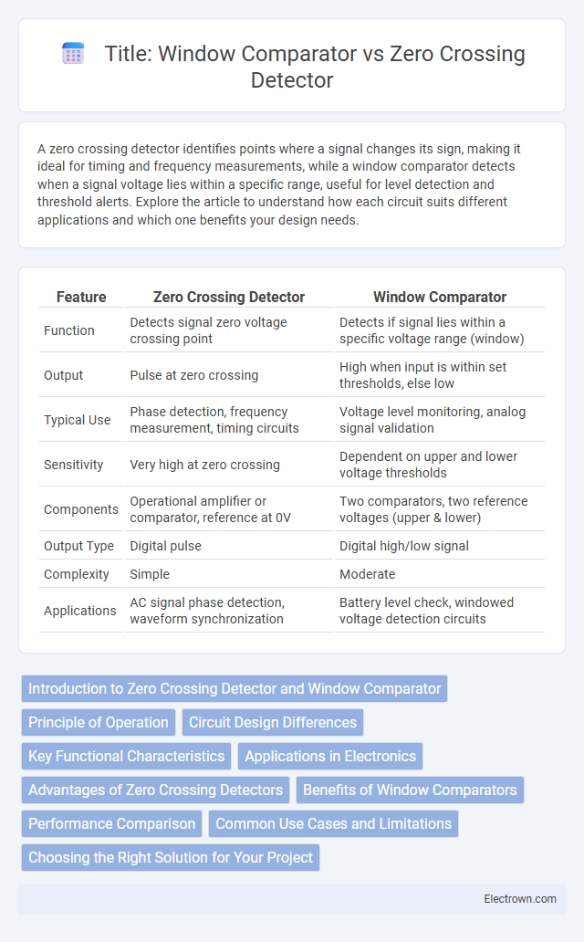
| Feature | Zero Crossing Detector | Window Comparator |
|---|---|---|
| Function | Detects signal zero voltage crossing point | Detects if signal lies within a specific voltage range (window) |
| Output | Pulse at zero crossing | High when input is within set thresholds, else low |
| Typical Use | Phase detection, frequency measurement, timing circuits | Voltage level monitoring, analog signal validation |
| Sensitivity | Very high at zero crossing | Dependent on upper and lower voltage thresholds |
| Components | Operational amplifier or comparator, reference at 0V | Two comparators, two reference voltages (upper & lower) |
| Output Type | Digital pulse | Digital high/low signal |
| Complexity | Simple | Moderate |
| Applications | AC signal phase detection, waveform synchronization | Battery level check, windowed voltage detection circuits |
Introduction to Zero Crossing Detector and Window Comparator
A Zero Crossing Detector is an electronic circuit designed to identify the point where an AC signal crosses the zero voltage level, making it essential for phase-locked loops and timing applications. A Window Comparator, on the other hand, monitors whether an input signal falls within a specific voltage range defined by two reference levels, useful for safety systems and signal validation. Understanding these fundamental differences helps you choose the right device for precise signal monitoring and control tasks.
Principle of Operation
A zero crossing detector operates by identifying the precise moment an input signal crosses the zero voltage level, converting the AC waveform into a digital pulse through a comparator with zero reference. A window comparator monitors whether an input voltage lies within a specified high and low threshold range, providing a binary output indicating if the signal is inside or outside this window. Your choice depends on whether detecting signal polarity changes (zero crossing) or voltage range boundaries (window comparator) is critical for your application.
Circuit Design Differences
Zero crossing detectors use an operational amplifier or comparator to detect when an input signal crosses zero volts, resulting in a simple circuit design with one reference level at zero. Window comparators employ two comparators with distinct upper and lower threshold voltages to determine if an input signal resides within a specific voltage range, leading to a more complex design involving dual reference points. Your choice depends on whether you require detection of zero voltage crossings or identifying signals within a particular voltage window.
Key Functional Characteristics
A zero crossing detector outputs a signal each time the input waveform crosses the zero voltage level, enabling precise detection of signal phase changes and frequency measurement. In contrast, a window comparator detects when an input voltage lies within or outside predefined upper and lower thresholds, providing a digital output that indicates whether the signal is inside or outside the specified voltage window. Zero crossing detectors are typically used for phase-locked loops and timing applications, whereas window comparators are essential in over-voltage protection, signal conditioning, and range detection systems.
Applications in Electronics
Zero crossing detectors are widely used in phase-locked loops, frequency measurement, and AC signal synchronization by detecting the exact point where the waveform crosses zero voltage. Window comparators find applications in voltage monitoring, battery level detection, and sensor interfacing by determining whether an input signal falls within a specific voltage range. Both circuits enhance circuit precision and control in digital communication systems, power electronics, and analog signal processing.
Advantages of Zero Crossing Detectors
Zero crossing detectors offer precise detection of signal phase changes, enabling accurate timing control in AC circuits and signal processing. Their simple design reduces circuit complexity and power consumption compared to window comparators, which require dual threshold levels for operation. These detectors provide fast response times with minimal distortion, making them ideal for phase-locked loops and frequency measurement applications.
Benefits of Window Comparators
Window comparators offer precise voltage monitoring by detecting if an input signal remains within a defined voltage range, enhancing measurement accuracy and system reliability. They provide greater noise immunity compared to zero crossing detectors, reducing false triggering in fluctuating signal environments. This capability is essential in applications requiring strict voltage threshold detection, such as battery monitoring and industrial automation.
Performance Comparison
Zero crossing detectors provide fast and precise detection of signal transitions at the zero voltage level, making them ideal for synchronization in AC systems and phase-locked loops. Window comparators offer better noise immunity and can detect when signals remain within a specific voltage range, enhancing performance in fault detection or threshold monitoring applications. Your choice depends on whether precise timing (zero crossing detectors) or range validation (window comparators) is more critical to your system's performance requirements.
Common Use Cases and Limitations
Zero crossing detectors are commonly used in AC signal processing, motor speed control, and phase-locked loops due to their precise timing of waveform transitions from positive to negative. Window comparators are preferred in sensor signal conditioning and threshold detection, as they monitor if an input voltage lies within a specific range, providing a robust alert system. Your choice depends on whether you need to detect waveform polarity changes or voltage ranges, with zero crossing detectors limited by noise sensitivity and window comparators constrained by fixed threshold settings.
Choosing the Right Solution for Your Project
Choosing between a zero crossing detector and a window comparator depends on the specific requirements of your project, such as signal type and threshold sensitivity. Zero crossing detectors excel in identifying precise moments when an AC signal crosses the zero-voltage level, making them ideal for phase-locked loops and timing applications. Window comparators provide more flexibility by detecting when a signal lies within a defined voltage range, suitable for fault detection and analog-to-digital conversion boundary monitoring.
Zero crossing detector vs window comparator Infographic