Common mode noise occurs when unwanted signals are present equally on both lines of a differential pair, while differential noise appears as a voltage difference between those lines, directly affecting signal integrity. Understanding the distinctions between common mode and differential noise is crucial for improving Your system's noise immunity and performance--read on to explore effective noise reduction techniques.
Table of Comparison
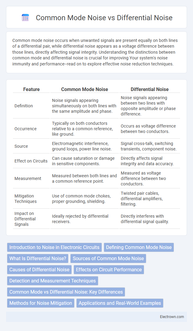
| Feature | Common Mode Noise | Differential Noise |
|---|---|---|
| Definition | Noise signals appearing simultaneously on both lines with the same amplitude and phase. | Noise signals appearing between two lines with opposite amplitude or phase difference. |
| Occurrence | Typically on both conductors relative to a common reference, like ground. | Occurs as voltage difference between two conductors. |
| Source | Electromagnetic interference, ground loops, power line noise. | Signal cross-talk, switching transients, component noise. |
| Effect on Circuits | Can cause saturation or damage in sensitive components. | Directly affects signal integrity and data accuracy. |
| Measurement | Measured between both lines and a common reference point. | Measured as voltage difference between two conductors. |
| Mitigation Techniques | Use of common mode chokes, proper grounding, shielding. | Twisted pair cables, differential amplifiers, filtering. |
| Impact on Differential Signals | Ideally rejected by differential receivers. | Directly interferes with differential signal quality. |
Introduction to Noise in Electronic Circuits
Noise in electronic circuits fundamentally affects signal integrity and system performance, with common mode noise and differential noise representing two primary types. Common mode noise occurs equally on both signal lines relative to ground, often due to external electromagnetic interference, while differential noise appears as a voltage difference between the two lines, typically originating from intrinsic circuit disturbances. Understanding these noise mechanisms is crucial for designing effective filtering and noise reduction strategies in sensitive electronic applications.
Defining Common Mode Noise
Common mode noise refers to unwanted signals that simultaneously appear and propagate with the same amplitude and phase on two or more lines relative to a common reference, often ground. This type of noise commonly arises from external electromagnetic interference or ground potential differences, affecting the overall signal integrity in communication and power systems. Understanding how common mode noise differs from differential noise, which occurs as opposite signals on paired lines, is essential for designing effective noise mitigation strategies to protect your electronic circuits.
What Is Differential Noise?
Differential noise, also known as normal mode noise, refers to the unwanted electrical signals that appear equally and oppositely on two conductors within a differential pair, causing interference in the intended signal transmission. It differs from common mode noise, which affects both conductors equally and in phase. Differential noise is critical in differential signaling systems because it directly impacts signal integrity and can degrade communication quality if not properly managed.
Sources of Common Mode Noise
Common mode noise originates from electromagnetic interference affecting both lines of a differential pair identically, often caused by power supply fluctuations, ground loops, or external radio frequency interference. Sources include switching power supplies, fluorescent lighting, and nearby motors that induce noise through capacitively or inductively coupling into circuit paths. Understanding these sources helps you implement effective filtering and shielding strategies to minimize common mode noise impact on signal integrity.
Causes of Differential Noise
Differential noise originates from uneven signal paths or mismatched impedance in circuits, causing voltage differences between two points that carry the intended signals. Sources include crosstalk from adjacent conductors, component tolerances, and external electromagnetic interference affecting only one signal line. Understanding these causes helps you design balanced systems that minimize differential noise and improve signal integrity.
Effects on Circuit Performance
Common mode noise causes interference by affecting both signal lines equally, leading to reduced signal integrity and increased electromagnetic interference in sensitive circuits. Differential noise impacts the voltage difference between two conductors, causing distortion and errors in analog and digital signal processing. Effective filtering and proper PCB layout techniques are essential to minimize both common mode and differential noise, ensuring optimal circuit performance and reliability.
Detection and Measurement Techniques
Common mode noise is detected using differential amplifiers configured to reject signals appearing simultaneously on both lines, isolating noise that is common to the system. Differential noise measurement employs instrumentation amplifiers or differential probes to capture signals present with opposite polarity on paired conductors, providing high sensitivity to symmetrical disturbances. Precision vector network analyzers and spectrum analyzers further quantify noise amplitudes and frequencies, enabling accurate discrimination between common mode and differential noise sources.
Common Mode vs Differential Noise: Key Differences
Common mode noise occurs when unwanted signals appear identically on both lines of a differential pair relative to a common ground, while differential noise appears as opposite signals on each line, affecting their difference. Common mode noise is often caused by external electromagnetic interference and can be minimized using shielding and common mode chokes. Differential noise impacts signal integrity directly and is typically mitigated through careful circuit design and differential signal processing techniques.
Methods for Noise Mitigation
Common mode noise mitigation techniques include the use of common mode chokes, shielded cables, and proper grounding to reduce interference by blocking noise that appears equally on both lines. Differential noise is effectively minimized through differential signaling, balanced transmission lines, and active filtering methods that target noise differences between signals. You can enhance signal integrity by combining these approaches tailored to the specific noise environment and system design requirements.
Applications and Real-World Examples
Common mode noise is prevalent in power supply lines and communication cables, often affecting data integrity in industrial automation and audio equipment, where single-ended signals are used. Differential noise appears primarily in balanced transmission systems like twisted-pair Ethernet cables and differential signaling in high-speed data interfaces, improving noise immunity and signal quality in networking and telecommunications. Real-world applications leverage common mode chokes to filter noise in automotive electronics, while differential amplifiers are essential in medical devices such as ECG machines for accurate signal detection.
common mode noise vs differential noise Infographic