Thermal noise, generated by the random motion of electrons in a conductor, presents a consistent, white noise spectrum across frequencies, whereas flicker noise, or 1/f noise, dominates at low frequencies and arises from defects and impurities in electronic components. Understanding these noise types is crucial for optimizing your electronic circuit's performance; explore the rest of the article to learn detailed characteristics and mitigation techniques.
Table of Comparison
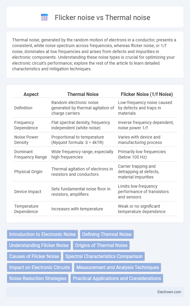
| Aspect | Thermal Noise | Flicker Noise (1/f Noise) |
|---|---|---|
| Definition | Random electronic noise generated by thermal agitation of charge carriers | Low-frequency noise caused by defects and traps in materials |
| Frequency Dependence | Flat spectral density, frequency independent (white noise) | Inverse frequency dependent, noise power 1/f |
| Noise Power Density | Proportional to temperature (Nyquist formula: S = 4kTR) | Varies with device and manufacturing process |
| Dominant Frequency Range | Wide frequency range, especially high frequencies | Primarily low frequencies (below 100 Hz) |
| Physical Origin | Thermal agitation of electrons in resistors and conductors | Carrier trapping and detrapping at defects, material impurities |
| Device Impact | Sets fundamental noise floor in resistors, amplifiers | Limits low-frequency performance of transistors and sensors |
| Temperature Dependence | Increases with temperature | Weak or no significant temperature dependence |
Introduction to Electronic Noise
Thermal noise, also known as Johnson-Nyquist noise, originates from the random motion of electrons in a conductor and is proportional to temperature and resistance. Flicker noise, or 1/f noise, stems from defects and traps in semiconductor materials and dominates at low frequencies. Understanding these noise types helps you optimize electronic circuit design for better signal integrity and performance.
Defining Thermal Noise
Thermal noise, also known as Johnson-Nyquist noise, arises from the random motion of electrons in a conductor due to thermal agitation, producing a white noise spectrum. It is proportional to the temperature and resistance, characterized by the formula Vn = (4kTRDf), where k is Boltzmann's constant, T the absolute temperature, R the resistance, and Df the bandwidth. Unlike flicker noise, which dominates at low frequencies and depends on device-specific defects and imperfections, thermal noise is frequency-independent and intrinsic to all resistive components.
Understanding Flicker Noise
Flicker noise, also known as 1/f noise, dominates at low frequencies and arises from defects and traps within semiconductor materials, causing fluctuations in carrier density and mobility. Unlike thermal noise, which has a flat spectral density and is temperature-dependent, flicker noise exhibits a spectral density inversely proportional to frequency and is heavily influenced by device fabrication and surface states. Understanding flicker noise is critical for optimizing low-frequency analog circuits, such as operational amplifiers and sensors, where minimizing long-term signal drift and improving stability are essential.
Origins of Thermal Noise
Thermal noise, also known as Johnson-Nyquist noise, originates from the random motion of charge carriers in a conductor due to thermal agitation at any temperature above absolute zero. This noise is caused by the intrinsic resistance in electronic components and is proportional to temperature, bandwidth, and resistance. Unlike flicker noise, which arises from defects and impurities, thermal noise is fundamental and unavoidable in all resistive materials.
Causes of Flicker Noise
Flicker noise, also known as 1/f noise, arises primarily from charge carrier traps and defects within semiconductor materials, causing fluctuations in current flow over time. Unlike thermal noise, which results from the random motion of electrons due to temperature, flicker noise is related to physical imperfections and surface states in devices such as transistors. These defects create varying resistance and capacitance, leading to low-frequency signal disturbances critical in sensitive electronic circuits.
Spectral Characteristics Comparison
Thermal noise exhibits a flat power spectral density across a wide frequency range, characterized as white noise due to its constant power per hertz. Flicker noise, also known as 1/f noise, shows a power spectral density inversely proportional to frequency, with higher energy concentrated at low frequencies. The spectral contrast between thermal noise's uniform distribution and flicker noise's frequency-dependent decline is critical in electronic circuit design and signal processing.
Impact on Electronic Circuits
Thermal noise, caused by the random motion of charge carriers, introduces a constant baseline noise level that limits the sensitivity and precision of electronic circuits, especially in high-frequency and low-signal applications. Flicker noise, also known as 1/f noise, dominates at low frequencies and significantly affects the stability and accuracy of amplifiers, oscillators, and sensors by causing drift and signal distortion. Minimizing the impact of these noise sources involves optimizing device materials, circuit design, and operating conditions to enhance overall performance and reliability.
Measurement and Analysis Techniques
Thermal noise is typically measured using spectrum analyzers by observing its uniform power spectral density over a wide frequency range, enabling straightforward quantification through root mean square (RMS) voltage calculations. Flicker noise, characterized by its 1/f frequency dependence, requires low-frequency noise measurement techniques such as lock-in amplifiers or specialized low-frequency noise analyzers to accurately capture its power spectrum and time-domain fluctuations. Advanced analysis often employs logarithmic frequency scaling and Allan variance to separate flicker noise contributions from thermal noise in precision electronic device characterization.
Noise Reduction Strategies
Thermal noise can be reduced by lowering the temperature of the electronic components or using precision resistors with lower values to minimize random electron movement. Flicker noise, also known as 1/f noise, can be mitigated by choosing high-quality materials like metal film resistors and implementing proper circuit design techniques such as chopper stabilization or auto-zero amplifiers. Your noise reduction strategy should prioritize the specific noise type impacting your device for effective enhancement of signal clarity.
Practical Applications and Considerations
Thermal noise, stemming from random electron motion, dominates high-frequency circuits like RF amplifiers and precision resistors, requiring careful thermal management and component selection to minimize signal distortion. Flicker noise, or 1/f noise, becomes significant in low-frequency applications such as operational amplifiers and sensor interfaces, influencing long-term signal stability and demanding specialized design techniques like chopper stabilization. Engineers must balance these noise types to optimize analog and mixed-signal systems, ensuring reliable performance in diverse practical scenarios.
Thermal noise vs flicker noise Infographic