Voltage divider bias offers stable operating point control by using two resistors to create a fixed base voltage, minimizing variations due to temperature or transistor beta changes, whereas emitter bias uses a single resistor in the emitter leg to provide negative feedback and improve stability but less precision. Understanding these differences can help you optimize transistor biasing for your specific circuit needs; explore the rest of the article for detailed comparisons and practical applications.
Table of Comparison
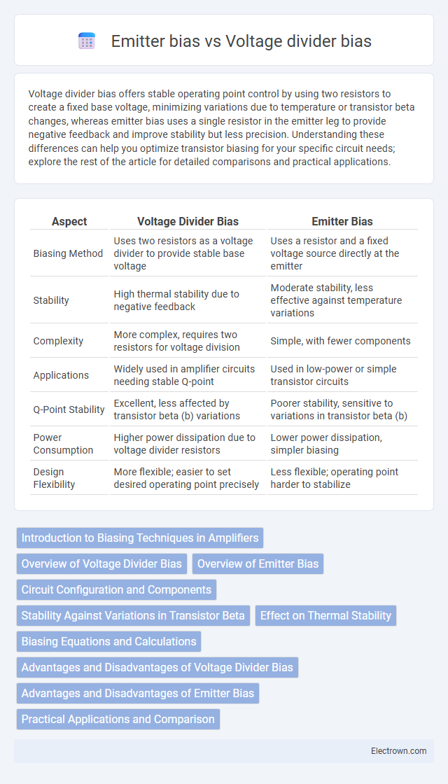
| Aspect | Voltage Divider Bias | Emitter Bias |
|---|---|---|
| Biasing Method | Uses two resistors as a voltage divider to provide stable base voltage | Uses a resistor and a fixed voltage source directly at the emitter |
| Stability | High thermal stability due to negative feedback | Moderate stability, less effective against temperature variations |
| Complexity | More complex, requires two resistors for voltage division | Simple, with fewer components |
| Applications | Widely used in amplifier circuits needing stable Q-point | Used in low-power or simple transistor circuits |
| Q-Point Stability | Excellent, less affected by transistor beta (b) variations | Poorer stability, sensitive to variations in transistor beta (b) |
| Power Consumption | Higher power dissipation due to voltage divider resistors | Lower power dissipation, simpler biasing |
| Design Flexibility | More flexible; easier to set desired operating point precisely | Less flexible; operating point harder to stabilize |
Introduction to Biasing Techniques in Amplifiers
Voltage divider bias provides a stable operating point by using two resistors to create a fixed voltage at the transistor base, minimizing variations due to temperature or transistor replacement. Emitter bias employs a single resistor in the emitter leg to improve thermal stability but is more sensitive to transistor parameter changes. Both techniques are essential for setting the correct Q-point in transistor amplifiers, ensuring consistent amplification performance.
Overview of Voltage Divider Bias
Voltage divider bias provides a stable operating point for bipolar junction transistors by using two resistors to create a voltage divider network that sets the base voltage. This biasing method improves thermal stability and reduces variation in transistor parameters compared to emitter bias. It is widely preferred in amplifier circuits for consistent performance under varying temperature and transistor beta changes.
Overview of Emitter Bias
Emitter bias uses a resistor connected to the emitter of a transistor, creating stable operating points through negative feedback that improves thermal stability. This method stabilizes the transistor's quiescent current and voltage, reducing variations caused by temperature changes or device parameter shifts. Your circuit benefits from enhanced reliability and consistent performance compared to simple voltage divider bias configurations.
Circuit Configuration and Components
Voltage divider bias uses two resistors connected in series to form a stable voltage at the base of the transistor, ensuring consistent biasing regardless of variations in transistor parameters. Emitter bias employs a single resistor in the emitter leg combined with a base resistor, relying on the voltage drop across the emitter resistor to stabilize the operating point. Voltage divider bias offers better thermal stability due to a fixed voltage reference, while emitter bias is simpler but more sensitive to parameter variations.
Stability Against Variations in Transistor Beta
Voltage divider bias offers superior stability against variations in transistor beta due to the fixed voltage established by the resistor network, which maintains a consistent base voltage independent of transistor gain changes. Emitter bias relies more heavily on the transistor's beta value, resulting in less predictable operating points as beta varies across devices or with temperature. The improved stability in voltage divider bias makes it preferable for circuits requiring reliable performance despite manufacturing tolerances and thermal effects impacting transistor gain.
Effect on Thermal Stability
Voltage divider bias offers superior thermal stability by maintaining a nearly constant voltage at the base, minimizing variations in collector current due to temperature changes. In contrast, emitter bias provides less thermal stability because the biasing relies more on the base resistor, making the collector current more sensitive to temperature fluctuations. The inclusion of an emitter resistor in both methods improves thermal stability, but the voltage divider bias configuration inherently compensates better for thermal variations.
Biasing Equations and Calculations
Voltage divider bias utilizes two resistors to establish a stable base voltage, expressed by the equation V_B = V_CC * (R2 / (R1 + R2)), ensuring consistent Q-point regardless of transistor beta variations. Emitter bias combines a resistor in the emitter leg and a base resistor, where base current I_B is approximated by (V_CC - V_BE) / (R_B + (b + 1) * R_E), making biasing sensitive to transistor beta. Calculations for voltage divider bias emphasize fixed base voltage and emitter voltage stabilization, while emitter bias relies on the feedback through the emitter resistor to stabilize operating point.
Advantages and Disadvantages of Voltage Divider Bias
Voltage divider bias provides excellent stability against variations in transistor beta (b) and temperature, making it widely used in amplifier circuits for consistent operating points. Its primary advantage is the fixed bias point, which minimizes distortion and enhances linearity by maintaining a nearly constant emitter current. However, the complexity of the resistor network increases circuit design effort and component count, leading to higher power consumption compared to simpler biasing methods like emitter bias.
Advantages and Disadvantages of Emitter Bias
Emitter bias offers improved thermal stability and better bias point control compared to voltage divider bias, making it more reliable in varying temperature conditions. However, emitter bias can result in lower voltage gain and increased power dissipation due to the additional emitter resistor. Your choice depends on the need for stability versus gain efficiency in amplifier design.
Practical Applications and Comparison
Voltage divider bias is widely used in amplifier circuits due to its stable operating point and reduced sensitivity to transistor beta variations, making it ideal for consistent signal amplification in audio and radio frequency applications. Emitter bias, while simpler and offering moderate stability through emitter resistance, finds practical use in low-cost or less critical circuits where precise biasing is not paramount. Compared to emitter bias, voltage divider bias provides superior thermal stability and predictable performance, essential in integrated circuits and communication devices.
Voltage divider bias vs emitter bias Infographic