Push-pull amplifiers provide high efficiency and low distortion by using complementary transistors that alternately drive the output, while totem-pole outputs arrange transistors vertically to enable fast switching and drive capabilities in digital circuits. Exploring these differences will help you understand which configuration suits your application's performance and design needs--read on to learn more.
Table of Comparison
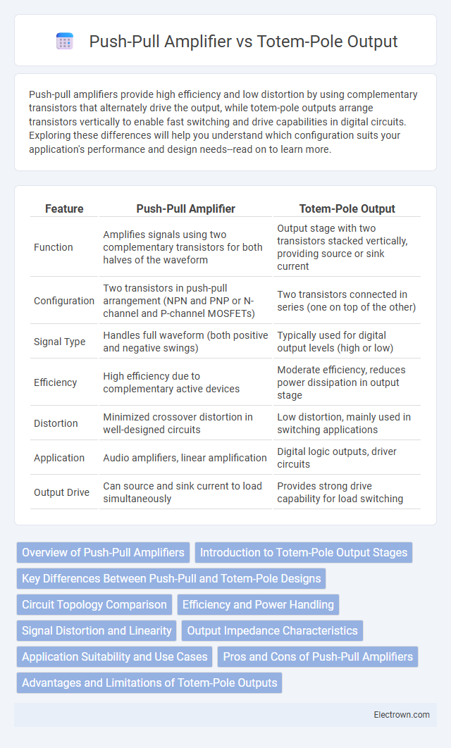
| Feature | Push-Pull Amplifier | Totem-Pole Output |
|---|---|---|
| Function | Amplifies signals using two complementary transistors for both halves of the waveform | Output stage with two transistors stacked vertically, providing source or sink current |
| Configuration | Two transistors in push-pull arrangement (NPN and PNP or N-channel and P-channel MOSFETs) | Two transistors connected in series (one on top of the other) |
| Signal Type | Handles full waveform (both positive and negative swings) | Typically used for digital output levels (high or low) |
| Efficiency | High efficiency due to complementary active devices | Moderate efficiency, reduces power dissipation in output stage |
| Distortion | Minimized crossover distortion in well-designed circuits | Low distortion, mainly used in switching applications |
| Application | Audio amplifiers, linear amplification | Digital logic outputs, driver circuits |
| Output Drive | Can source and sink current to load simultaneously | Provides strong drive capability for load switching |
Overview of Push-Pull Amplifiers
Push-pull amplifiers utilize two active devices that alternately amplify opposite halves of the input signal, improving efficiency and reducing even-order harmonics. They are widely used in audio amplification and radio frequency applications due to their ability to deliver higher power output with low distortion. The design inherently cancels certain types of nonlinear distortion, making push-pull configurations favorable over single-ended amplifiers in high-fidelity settings.
Introduction to Totem-Pole Output Stages
Totem-pole output stages consist of two transistors stacked vertically, providing both sourcing and sinking current capability for efficient signal amplification. This configuration enhances voltage swing and improves linearity compared to push-pull amplifiers, which rely on separate transistor pairs for positive and negative halves of the waveform. Understanding totem-pole output stages helps you optimize amplifier designs for higher gain and lower distortion in audio and power applications.
Key Differences Between Push-Pull and Totem-Pole Designs
Push-pull amplifiers use a pair of transistors that alternately amplify opposite halves of the signal waveform, minimizing distortion and improving efficiency. Totem-pole output stages stack transistors vertically to provide both sourcing and sinking current capabilities in a single branch, optimizing output drive strength and speed. While push-pull designs excel in linear audio amplification, totem-pole outputs are commonly found in digital logic circuits where fast switching and low output impedance are critical.
Circuit Topology Comparison
Push-pull amplifiers utilize two active devices that alternately drive the output, effectively reducing distortion by canceling even harmonics and improving efficiency in Class B and AB operation. Totem-pole output stages stack transistors in a complementary arrangement, allowing seamless transition between sourcing and sinking current to the load, often found in digital logic circuits to achieve fast switching with low output impedance. Your choice between push-pull and totem-pole configurations depends on whether the priority lies in linear amplification quality or rapid digital signal transitions.
Efficiency and Power Handling
Push-pull amplifiers offer higher power handling by driving both halves of the waveform separately, reducing distortion and improving overall efficiency compared to single-ended designs. Totem-pole outputs, commonly used in digital and audio circuits, provide efficient switching capabilities but typically handle lower power levels and may generate more heat under continuous high load. The push-pull configuration excels in delivering greater output power with enhanced thermal management, making it suitable for high-power audio amplification.
Signal Distortion and Linearity
Push-pull amplifiers reduce signal distortion effectively by driving complementary devices in opposite phases, which cancels even-order harmonics and improves linearity. Totem-pole output stages, commonly used in digital circuits, may introduce non-linearities due to transistor switching characteristics, leading to higher distortion in analog signals. Optimizing linearity in push-pull configurations enhances audio fidelity and signal integrity crucial for high-performance amplification.
Output Impedance Characteristics
Push-pull amplifiers typically exhibit lower output impedance due to their complementary transistor pairs actively driving both halves of the waveform, which improves linearity and power efficiency. Totem-pole output stages often feature a higher output impedance because the transistors switch alternately in a stacked configuration, affecting the signal drive under varying load conditions. Understanding these output impedance characteristics helps optimize your amplifier design for better frequency response and load matching.
Application Suitability and Use Cases
Push-pull amplifiers excel in high-power audio applications and RF transmitters due to their efficient distortion reduction and balanced output, ideal for driving speakers or radio signals. Totem-pole outputs are commonly found in digital logic circuits and power supplies, where fast switching and low output impedance are crucial for driving capacitive loads or interfacing logic gates. Your choice depends on whether you prioritize audio fidelity and power handling (push-pull) or speed and digital signal integrity (totem-pole).
Pros and Cons of Push-Pull Amplifiers
Push-pull amplifiers offer high efficiency and reduced even-order harmonic distortion by using complementary transistors to amplify both halves of the waveform, resulting in improved audio fidelity. However, they can suffer from crossover distortion at the zero-crossing point and require precise transistor matching and biasing, complicating the design process. Despite these challenges, push-pull amplifiers are favored in high-power audio applications for their ability to deliver strong output power with balanced performance.
Advantages and Limitations of Totem-Pole Outputs
Totem-pole outputs provide the advantage of fast switching speeds and efficient use of transistor components, making them ideal for digital logic circuits and high-frequency applications. Their design allows for low output impedance and reduced power loss during transitions, enhancing signal integrity. However, totem-pole outputs can be susceptible to shoot-through current during switching, potentially causing increased power consumption and thermal stress in your electronic circuits.
Push-pull amplifier vs totem-pole output Infographic