A CAN transceiver handles the physical layer by converting digital data from the CAN controller into signals on the CAN bus, ensuring reliable communication between devices, while the CAN controller manages the data link layer by formatting and interpreting messages according to the CAN protocol. Understanding the distinct roles of these components is crucial for optimizing your vehicle or industrial network performance; discover more about their functions and differences in the full article.
Table of Comparison
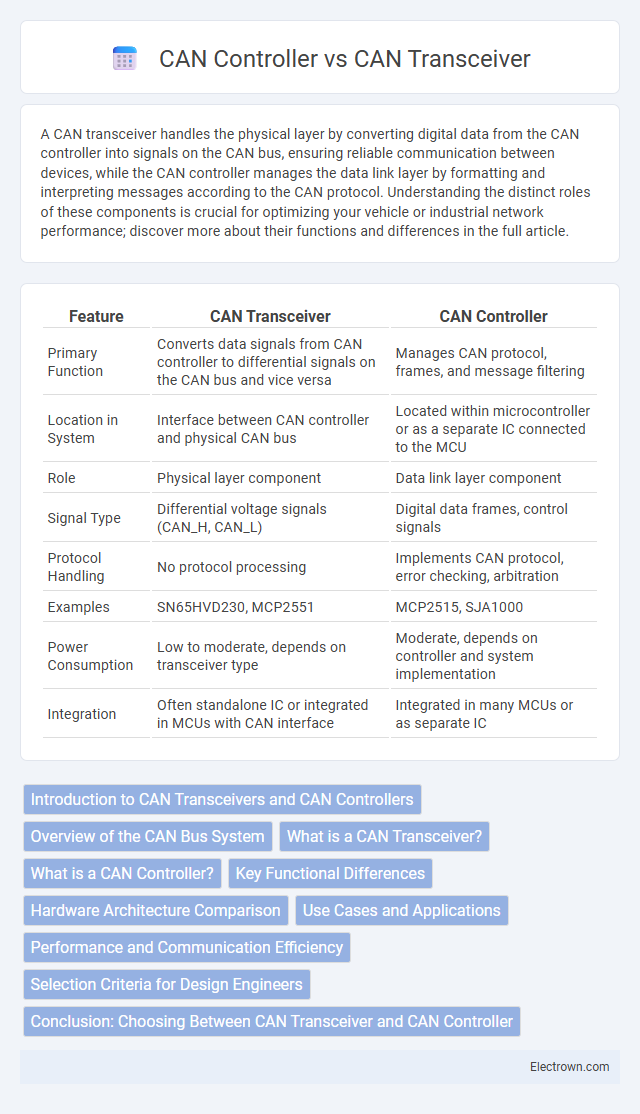
| Feature | CAN Transceiver | CAN Controller |
|---|---|---|
| Primary Function | Converts data signals from CAN controller to differential signals on the CAN bus and vice versa | Manages CAN protocol, frames, and message filtering |
| Location in System | Interface between CAN controller and physical CAN bus | Located within microcontroller or as a separate IC connected to the MCU |
| Role | Physical layer component | Data link layer component |
| Signal Type | Differential voltage signals (CAN_H, CAN_L) | Digital data frames, control signals |
| Protocol Handling | No protocol processing | Implements CAN protocol, error checking, arbitration |
| Examples | SN65HVD230, MCP2551 | MCP2515, SJA1000 |
| Power Consumption | Low to moderate, depends on transceiver type | Moderate, depends on controller and system implementation |
| Integration | Often standalone IC or integrated in MCUs with CAN interface | Integrated in many MCUs or as separate IC |
Introduction to CAN Transceivers and CAN Controllers
CAN transceivers serve as the physical layer interface in Controller Area Network (CAN) systems, converting digital signals from the CAN controller into differential signals on the network bus and vice versa, ensuring robust data transmission. CAN controllers handle the data link layer functions, managing message framing, error detection, and arbitration, which are critical for reliable communication between electronic control units (ECUs) in automotive and industrial applications. The collaboration between CAN transceivers and CAN controllers enables efficient and error-resilient communication, forming the foundation of modern CAN bus networks.
Overview of the CAN Bus System
The CAN transceiver serves as the physical interface between the CAN controller and the CAN bus, managing signal conversion and line driving to ensure reliable data transmission over the network. The CAN controller handles message framing, error detection, and arbitration within the CAN protocol, functioning as the microcontroller's communication core. Together, the transceiver and controller enable efficient and robust data exchange crucial for automotive and industrial CAN bus systems.
What is a CAN Transceiver?
A CAN transceiver is a crucial hardware component that facilitates communication between the CAN controller and the physical CAN bus by converting digital signals to differential voltage signals and vice versa. It ensures proper signal transmission and reception, maintaining data integrity across the network. Understanding your CAN transceiver's role is essential for optimizing the performance and reliability of CAN-based communication systems.
What is a CAN Controller?
A CAN Controller is a crucial component in the Controller Area Network (CAN) system responsible for managing data communication between the microcontroller and the CAN bus. It handles message framing, error detection, and arbitration, ensuring reliable and efficient data exchange. Your device relies on the CAN Controller to interpret incoming messages and prepare outgoing data according to the CAN protocol.
Key Functional Differences
A CAN transceiver primarily manages the physical layer by converting data signals between the CAN controller and the CAN bus, enabling reliable communication over the network. The CAN controller handles data link layer functions, including message framing, error detection, and arbitration, essential for protocol compliance and data integrity. Unlike the transceiver, the controller processes and organizes CAN messages, while the transceiver ensures electrical compatibility and signal transmission.
Hardware Architecture Comparison
The CAN transceiver serves as the physical layer interface, converting digital signals from the CAN controller into differential signals on the CAN bus, ensuring proper voltage levels and noise immunity. The CAN controller is responsible for processing the CAN protocol, including message framing, error detection, and arbitration, typically integrated within a microcontroller or as a standalone IC. Your hardware design benefits from separating these functions, allowing the transceiver to handle physical signaling while the controller manages data link layer tasks efficiently.
Use Cases and Applications
CAN transceivers enable reliable physical-layer communication by converting digital signals from the CAN controller into differential signals on the CAN bus, making them essential in automotive, industrial automation, and heavy machinery for real-time data exchange. CAN controllers handle message framing, error detection, and arbitration, facilitating communication protocols in embedded systems such as vehicle electronic control units (ECUs), robotics, and medical devices. Integration of both CAN transceiver and controller is critical in applications requiring robust network communication, including electric vehicles, factory automation, and avionics systems.
Performance and Communication Efficiency
CAN transceivers handle the physical layer by converting digital signals to differential signals for the CAN bus, directly influencing signal integrity and noise immunity, which enhances communication reliability. CAN controllers manage the data link layer, executing message framing, error detection, and arbitration, thus optimizing bus utilization and data throughput. High-performance CAN networks rely on efficient coordination between transceivers and controllers to minimize latency and maximize communication efficiency in real-time automotive and industrial applications.
Selection Criteria for Design Engineers
Design engineers should select a CAN transceiver based on voltage compatibility, data rate requirements up to 1 Mbps, and robustness against electromagnetic interference to ensure reliable physical layer communication. The CAN controller choice depends on microcontroller integration, supported protocols like CAN 2.0A/B or CAN FD, and available buffer sizes for message handling. Your design benefits from balancing the transceiver's hardware interface with the controller's software flexibility to optimize performance and cost.
Conclusion: Choosing Between CAN Transceiver and CAN Controller
Selecting between a CAN transceiver and a CAN controller depends on the specific requirements of the Controller Area Network system. The CAN transceiver manages the physical layer by converting digital signals from the CAN controller into differential signals on the CAN bus, ensuring robust communication. The CAN controller handles data link layer functions such as message framing, error detection, and arbitration, making it essential for protocol management within the microcontroller.
CAN transceiver vs CAN controller Infographic