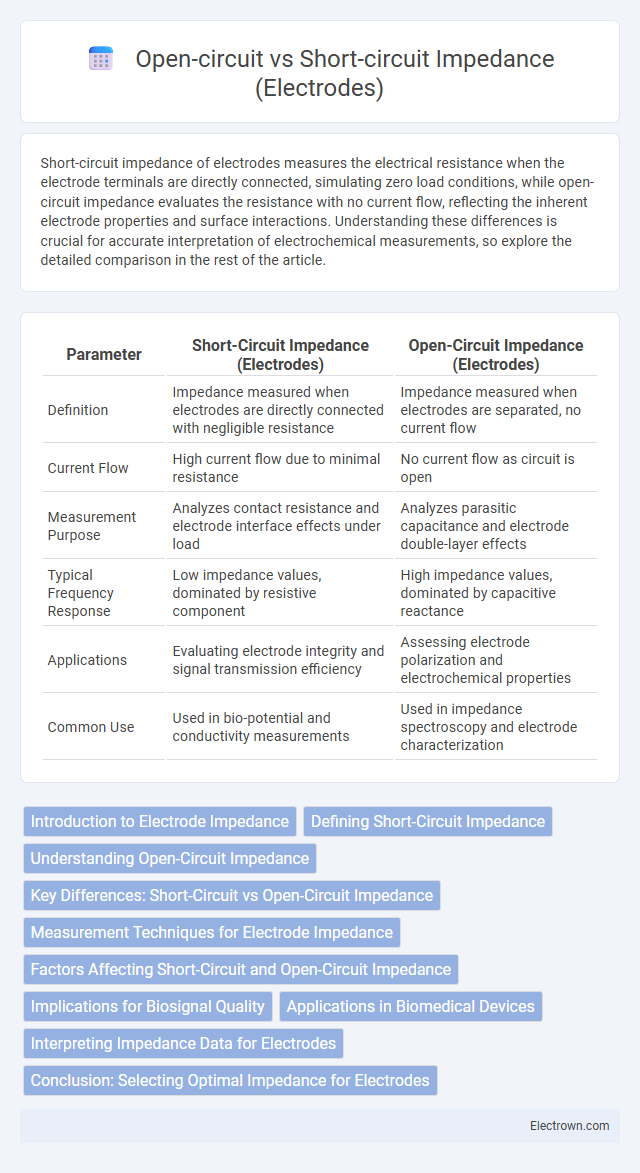
Short-circuit impedance of electrodes measures the electrical resistance when the electrode terminals are directly connected, simulating zero load conditions, while open-circuit impedance evaluates the resistance with no current flow, reflecting the inherent electrode properties and surface interactions. Understanding these differences is crucial for accurate interpretation of electrochemical measurements, so explore the detailed comparison in the rest of the article.
Table of Comparison
| Parameter | Short-Circuit Impedance (Electrodes) | Open-Circuit Impedance (Electrodes) |
|---|---|---|
| Definition | Impedance measured when electrodes are directly connected with negligible resistance | Impedance measured when electrodes are separated, no current flow |
| Current Flow | High current flow due to minimal resistance | No current flow as circuit is open |
| Measurement Purpose | Analyzes contact resistance and electrode interface effects under load | Analyzes parasitic capacitance and electrode double-layer effects |
| Typical Frequency Response | Low impedance values, dominated by resistive component | High impedance values, dominated by capacitive reactance |
| Applications | Evaluating electrode integrity and signal transmission efficiency | Assessing electrode polarization and electrochemical properties |
| Common Use | Used in bio-potential and conductivity measurements | Used in impedance spectroscopy and electrode characterization |
Introduction to Electrode Impedance
Electrode impedance is a critical parameter in bioelectrical measurements, representing the opposition to current flow at the electrode-tissue interface. Short-circuit impedance measures the electrode's resistance when its terminals are directly connected, reflecting intrinsic material properties and contact quality. Open-circuit impedance characterizes the electrode's behavior with no current flow, revealing capacitive and polarization effects crucial for accurate signal acquisition.
Defining Short-Circuit Impedance
Short-circuit impedance in electrodes refers to the resistance and reactance measured when the electrode terminals are directly connected with negligible resistance, typically approaching zero voltage across the terminals. This parameter is critical in evaluating the intrinsic electrode properties and interface impedance without external load influence, providing insight into the electrode's conductive pathways. Accurate assessment of short-circuit impedance helps in optimizing electrode materials and configurations for applications such as bioelectrical measurements and electrochemical sensors.
Understanding Open-Circuit Impedance
Open-circuit impedance of electrodes measures the opposition to current flow when no external current is applied, reflecting inherent electrode properties and interface behavior. This impedance is critical in electrochemical systems as it influences signal quality and stability by representing capacitance and resistive elements at the electrode-electrolyte interface. Understanding your electrode's open-circuit impedance helps optimize sensor accuracy and device performance by identifying contact issues or material defects.
Key Differences: Short-Circuit vs Open-Circuit Impedance
Short-circuit impedance refers to the electrical resistance measured when the electrode terminals are directly connected, resulting in minimal impedance primarily influenced by the electrode material and contacts. Open-circuit impedance is measured with no electrical connection between terminals, reflecting the capacitive and dielectric properties of the electrode and surrounding medium. Key differences highlight that short-circuit impedance is generally lower and dominated by resistive factors, while open-circuit impedance is higher due to capacitive reactance and the absence of current flow.
Measurement Techniques for Electrode Impedance
Measurement techniques for electrode impedance involve analyzing both short-circuit and open-circuit conditions to accurately characterize electrode performance. Short-circuit impedance measurement typically uses a low-impedance reference to assess the electrode's real impedance, while open-circuit impedance employs high-impedance instruments to evaluate the electrode's capacitive and resistive properties without current flow. Understanding these measurement methods allows you to optimize electrode design and ensure precise bioelectrical signal acquisition.
Factors Affecting Short-Circuit and Open-Circuit Impedance
Short-circuit impedance in electrodes is primarily influenced by contact resistance, electrode material conductivity, and the quality of the electrode-skin interface, which affects the current flow path. Open-circuit impedance depends heavily on factors like electrode surface area, electrolyte composition, and the dielectric properties of the electrode insulation, impacting voltage measurement accuracy. Environmental conditions such as temperature and humidity also play a significant role in altering both short-circuit and open-circuit impedance characteristics.
Implications for Biosignal Quality
Short-circuit impedance in electrodes typically results in lower resistance and enhanced signal fidelity, improving biosignal quality by reducing noise and signal attenuation. Open-circuit impedance, on the other hand, is characterized by high resistance and potential signal distortion, which can degrade the accuracy and reliability of biosignal measurements. Optimizing electrode-skin impedance balance is crucial for producing high-quality, consistent biosignals necessary for accurate physiological monitoring.
Applications in Biomedical Devices
Short-circuit and open-circuit impedance measurements of electrodes are critical in optimizing biomedical devices such as ECG and EEG systems, where accurate signal acquisition is essential. Short-circuit impedance assesses the electrode-skin interface resistance, minimizing noise for clearer bio-signal transmission, while open-circuit impedance evaluates the electrode's ability to maintain signal integrity without current flow, enhancing device reliability. Understanding these impedance characteristics ensures your biomedical device delivers precise monitoring and effective patient care.
Interpreting Impedance Data for Electrodes
Interpreting impedance data for electrodes involves analyzing short-circuit impedance, which represents the minimum resistance when the electrode surfaces are in direct contact, versus open-circuit impedance, reflecting the maximum resistance when the electrodes are separated or insulated. Short-circuit impedance typically indicates the baseline conductive properties and contact quality, while open-circuit impedance reveals insulation integrity, electrode polarization effects, and capacitive behaviors. Accurate differentiation between these impedances allows for precise evaluation of electrode performance in bioelectrical measurements and helps in diagnosing issues such as corrosion, electrode degradation, or connection faults.
Conclusion: Selecting Optimal Impedance for Electrodes
Optimal impedance selection for electrodes depends on minimizing signal distortion and maximizing power transfer; short-circuit impedance typically offers low resistance but can introduce noise, whereas open-circuit impedance presents high resistance, reducing current flow and measurement accuracy. Balancing impedance values ensures enhanced electrode performance by optimizing signal fidelity and reducing artifacts in electrophysiological recordings. Selecting an impedance range around 1 kO to 10 kO is generally effective for maintaining sensitivity and stability in bioelectrical applications.
Short-circuit vs Open-circuit Impedance (Electrodes) Infographic