RF chokes and bypass capacitors serve distinct roles in electronic circuits; RF chokes block high-frequency signals while allowing DC current to pass, effectively filtering out unwanted RF interference, whereas bypass capacitors provide a low impedance path for high-frequency noise, stabilizing voltage supply lines. Understanding these components' functions can enhance your circuit design and troubleshooting skills--read on to explore their applications and differences in detail.
Table of Comparison
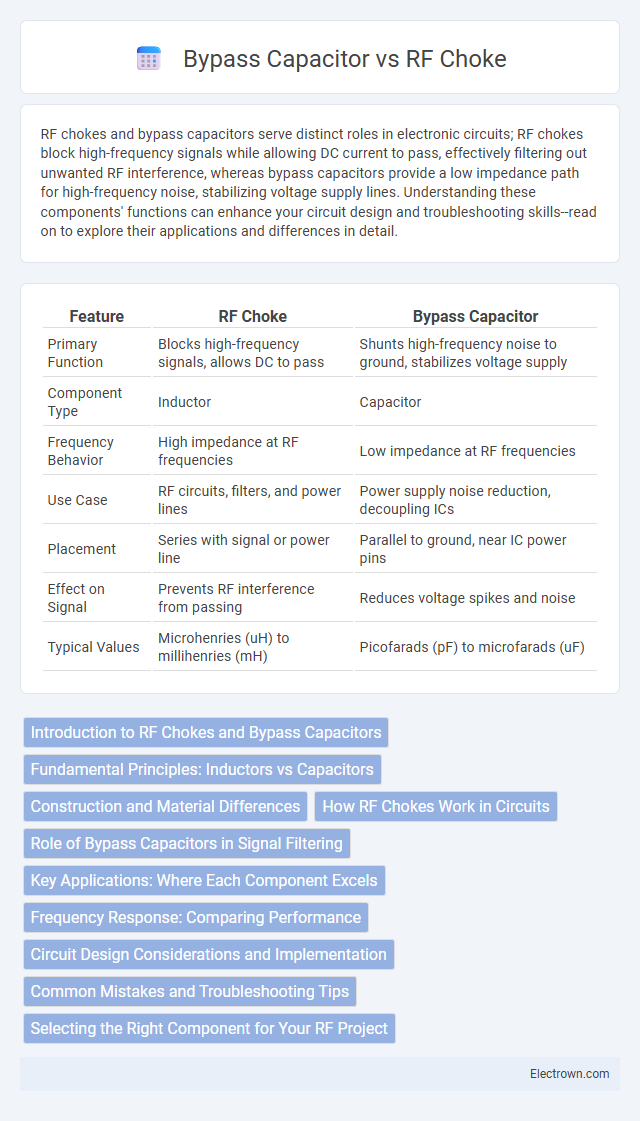
| Feature | RF Choke | Bypass Capacitor |
|---|---|---|
| Primary Function | Blocks high-frequency signals, allows DC to pass | Shunts high-frequency noise to ground, stabilizes voltage supply |
| Component Type | Inductor | Capacitor |
| Frequency Behavior | High impedance at RF frequencies | Low impedance at RF frequencies |
| Use Case | RF circuits, filters, and power lines | Power supply noise reduction, decoupling ICs |
| Placement | Series with signal or power line | Parallel to ground, near IC power pins |
| Effect on Signal | Prevents RF interference from passing | Reduces voltage spikes and noise |
| Typical Values | Microhenries (uH) to millihenries (mH) | Picofarads (pF) to microfarads (uF) |
Introduction to RF Chokes and Bypass Capacitors
RF chokes are inductors designed to block high-frequency AC signals while allowing DC currents to pass, commonly used in RF circuits to suppress interference and noise. Bypass capacitors provide a low impedance path to ground for high-frequency signals, effectively filtering out unwanted noise and stabilizing power supply lines. Both components work together in electronic circuits to enhance signal integrity and reduce electromagnetic interference.
Fundamental Principles: Inductors vs Capacitors
RF chokes use inductors to block high-frequency signals by presenting high impedance, while bypass capacitors provide a low-impedance path to ground for unwanted high-frequency noise, effectively filtering it out. Inductors store energy in a magnetic field, resisting rapid current changes, making them ideal for isolating RF signals. Capacitors store energy in an electric field, allowing high-frequency currents to bypass sensitive components, thus stabilizing your circuit's voltage.
Construction and Material Differences
RF chokes are typically constructed using inductive coils of wire wound around ferrite or powdered iron cores, designed to block high-frequency signals while allowing DC or low-frequency currents to pass. Bypass capacitors consist of ceramic, tantalum, or electrolytic materials that store and release electrical energy, effectively shunting high-frequency noise to ground. Your choice between these components depends on their distinct material properties and construction, which influence their filtering performance in RF circuits.
How RF Chokes Work in Circuits
RF chokes function by presenting high impedance to high-frequency signals, effectively blocking or attenuating RF currents while allowing DC or low-frequency signals to pass through. Constructed with inductors, RF chokes store energy in a magnetic field, which resists rapid changes in current, making them essential in filtering noise and preventing interference in RF circuits. Their placement in power supply lines or signal paths helps isolate RF signals, maintaining circuit integrity and improving overall performance.
Role of Bypass Capacitors in Signal Filtering
Bypass capacitors play a critical role in signal filtering by providing a low-impedance path to ground for high-frequency noise, thereby stabilizing the power supply voltage. They effectively suppress high-frequency interference and prevent noise from coupling into sensitive circuit components. Unlike RF chokes that block high-frequency signals, bypass capacitors filter out unwanted noise by shunting it away from the active circuit elements.
Key Applications: Where Each Component Excels
RF chokes excel in applications requiring the blocking of high-frequency signals while allowing DC current to pass, making them ideal for RF circuits and power supply filtering. Bypass capacitors are best suited for decoupling noise and stabilizing voltage in digital and analog circuits by shunting high-frequency disturbances to ground. Your choice depends on whether you need to block RF interference or smooth power supply variations in sensitive electronic designs.
Frequency Response: Comparing Performance
RF chokes provide high impedance at radio frequencies, effectively blocking unwanted high-frequency signals, while bypass capacitors offer low impedance paths to ground, shunting noise away from sensitive circuits. At frequencies above the choke's self-resonant frequency, its inductive reactance decreases, reducing its effectiveness, whereas bypass capacitors maintain low impedance up to their self-resonant frequency, ensuring better high-frequency noise suppression. Optimal frequency response in RF design requires combining RF chokes and bypass capacitors to balance impedance characteristics and achieve efficient noise filtering across a wide frequency spectrum.
Circuit Design Considerations and Implementation
In circuit design, an RF choke provides high impedance at radio frequencies, effectively blocking unwanted RF signals while allowing DC or low-frequency signals to pass, making it essential for noise suppression in RF power lines. A bypass capacitor offers a low-impedance path to ground for high-frequency signals, stabilizing voltage supply rails by filtering out voltage spikes and noise. When implementing these components, balance your layout to minimize parasitic inductance and capacitance, ensuring the RF choke and bypass capacitor are placed as close as possible to the active device for optimal noise reduction and signal integrity.
Common Mistakes and Troubleshooting Tips
Common mistakes when using RF chokes and bypass capacitors include selecting incorrect component values, leading to ineffective noise suppression or signal distortion. Troubleshooting often involves checking for poor PCB layout, such as long traces or improper placement, which can introduce parasitic inductance and reduce component efficacy. To optimize performance, ensure your RF choke and bypass capacitor are properly rated for your frequency range and are positioned close to the noise source or sensitive circuit nodes.
Selecting the Right Component for Your RF Project
Selecting the right component for your RF project involves understanding the distinct roles of RF chokes and bypass capacitors. An RF choke blocks high-frequency signals by presenting high impedance, effectively isolating parts of the circuit from RF noise, while a bypass capacitor provides a low impedance path to ground, filtering unwanted interference and stabilizing voltage supply. Your choice depends on whether you need to prevent RF signals from passing (use an RF choke) or to shunt noise and maintain signal integrity (use a bypass capacitor).
RF Choke vs Bypass Capacitor Infographic