Clock skew refers to the difference in timing between two clocks in a system, while clock jitter describes the variation in a clock signal's timing from its ideal position. Understanding these distinctions can help you optimize synchronization and performance in your electronic designs; read on to explore their impacts and mitigation techniques.
Table of Comparison
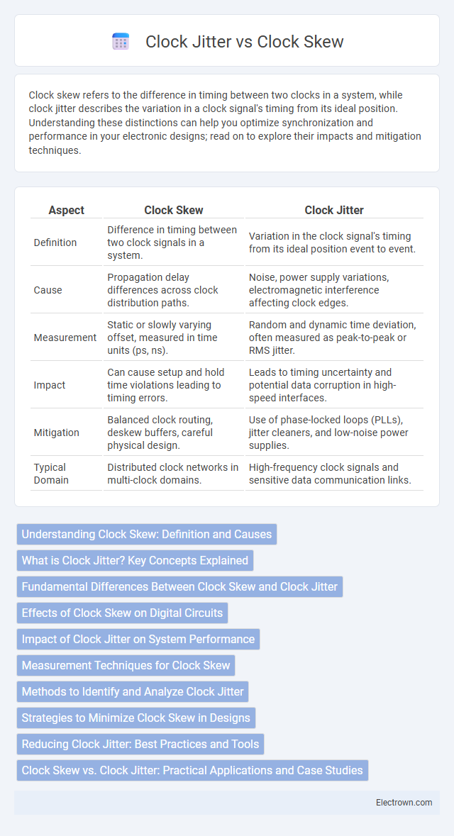
| Aspect | Clock Skew | Clock Jitter |
|---|---|---|
| Definition | Difference in timing between two clock signals in a system. | Variation in the clock signal's timing from its ideal position event to event. |
| Cause | Propagation delay differences across clock distribution paths. | Noise, power supply variations, electromagnetic interference affecting clock edges. |
| Measurement | Static or slowly varying offset, measured in time units (ps, ns). | Random and dynamic time deviation, often measured as peak-to-peak or RMS jitter. |
| Impact | Can cause setup and hold time violations leading to timing errors. | Leads to timing uncertainty and potential data corruption in high-speed interfaces. |
| Mitigation | Balanced clock routing, deskew buffers, careful physical design. | Use of phase-locked loops (PLLs), jitter cleaners, and low-noise power supplies. |
| Typical Domain | Distributed clock networks in multi-clock domains. | High-frequency clock signals and sensitive data communication links. |
Understanding Clock Skew: Definition and Causes
Clock skew refers to the time difference between the rising edges of clock signals in different parts of a synchronous circuit, often caused by variations in wire length, temperature changes, or manufacturing process inconsistencies. This discrepancy can lead to timing errors and data corruption if not properly managed in digital systems. Understanding the root causes of clock skew helps you design more reliable clock distribution networks, improving overall system performance.
What is Clock Jitter? Key Concepts Explained
Clock jitter refers to the small, rapid variations in a clock signal's timing, causing deviation from its ideal periodicity. It affects the stability and accuracy of timing circuits, influencing data transmission and synchronization in digital systems. Understanding jitter involves analyzing its sources, such as thermal noise and power supply fluctuations, and its impact on signal integrity and system performance.
Fundamental Differences Between Clock Skew and Clock Jitter
Clock skew refers to the timing difference between clock signals reaching different components in a synchronous system, causing phase discrepancies that can affect data synchronization. Clock jitter involves short-term variations in the clock signal's timing accuracy, resulting in unpredictable deviations from the expected clock edges. Your system's performance and reliability depend on minimizing both clock skew and clock jitter, as they impact signal integrity and timing margins in different ways.
Effects of Clock Skew on Digital Circuits
Clock skew causes timing mismatches between different parts of a digital circuit, leading to setup and hold time violations that can result in data corruption or logic errors. It increases the risk of metastability and reduces the overall reliability and performance of synchronous systems. Managing your clock distribution network is crucial to minimize skew and ensure synchronized operation across all circuit elements.
Impact of Clock Jitter on System Performance
Clock jitter causes timing variations that degrade signal integrity and increase bit error rates in high-speed communication systems. Its impact on system performance includes reduced data throughput and compromised synchronization accuracy, leading to potential data loss or malfunction. Managing your clock jitter is crucial to maintaining reliable system operation and optimal performance.
Measurement Techniques for Clock Skew
Clock skew measurement techniques often involve time interval analyzers or high-precision oscilloscopes that capture the timing difference between clock signals at various points in a digital system. Phase detection methods utilize phase-locked loops (PLLs) or time-to-digital converters (TDCs) to quantify clock skew by comparing clock edges precisely. Statistical analysis of timestamped events across multiple clock domains further enhances accuracy when assessing clock skew in complex integrated circuits.
Methods to Identify and Analyze Clock Jitter
Clock jitter can be identified and analyzed using time-domain and frequency-domain measurement techniques, such as oscilloscopes with jitter analysis software and phase noise analyzers. Methods like histogram analysis, Allan deviation, and spectral analysis enable precise characterization of jitter magnitude and frequency components. Understanding these measurement techniques helps you improve circuit performance by minimizing timing uncertainties caused by clock signal variations.
Strategies to Minimize Clock Skew in Designs
Minimizing clock skew in designs involves careful layout optimization, such as reducing trace length differences and using matched impedance routing to ensure signal integrity. Employing balanced clock tree synthesis and implementing clock distribution techniques like deskew buffers or phase-locked loops (PLLs) effectively align clock signals across components. Your design can achieve higher timing accuracy and reliability by prioritizing these strategies to reduce clock skew-related errors.
Reducing Clock Jitter: Best Practices and Tools
Reducing clock jitter is critical for maintaining signal integrity in high-speed digital systems and can be achieved through best practices such as using low phase noise oscillators, optimizing PCB layout to minimize electromagnetic interference, and employing proper power supply filtering. Tools like phase noise analyzers and jitter measurement instruments allow precise characterization of clock signals, enabling engineers to identify sources of jitter and implement targeted mitigation strategies. Techniques such as phase-locked loops (PLLs) with jitter attenuation features and spread spectrum clocking further enhance clock signal stability by reducing timing variations.
Clock Skew vs. Clock Jitter: Practical Applications and Case Studies
Clock skew, the timing difference between clocks in synchronous systems, is critical in multi-core processors and distributed networks to ensure data integrity and synchronization accuracy. Clock jitter, representing short-term variations in clock signal timing, plays a significant role in high-frequency communication systems like phase-locked loops and radio frequency circuits, affecting signal quality and error rates. Practical case studies in microprocessor design and telecommunications reveal that managing clock skew optimizes data transfer timing, while minimizing clock jitter enhances overall system reliability and performance.
Clock Skew vs Clock Jitter Infographic