Edge-triggered D flip-flops capture data at the moment of a clock edge, ensuring precise timing and minimizing delay, while master-slave D flip-flops use two stages to prevent race conditions and hold the output stable during the clock period. Explore the detailed differences between these flip-flop types to optimize Your digital circuit designs effectively.
Table of Comparison
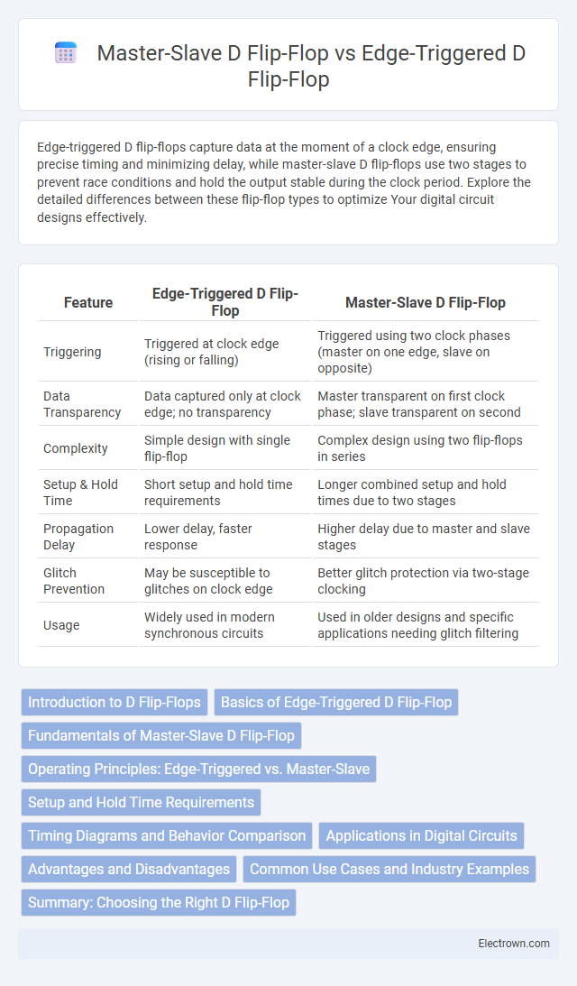
| Feature | Edge-Triggered D Flip-Flop | Master-Slave D Flip-Flop |
|---|---|---|
| Triggering | Triggered at clock edge (rising or falling) | Triggered using two clock phases (master on one edge, slave on opposite) |
| Data Transparency | Data captured only at clock edge; no transparency | Master transparent on first clock phase; slave transparent on second |
| Complexity | Simple design with single flip-flop | Complex design using two flip-flops in series |
| Setup & Hold Time | Short setup and hold time requirements | Longer combined setup and hold times due to two stages |
| Propagation Delay | Lower delay, faster response | Higher delay due to master and slave stages |
| Glitch Prevention | May be susceptible to glitches on clock edge | Better glitch protection via two-stage clocking |
| Usage | Widely used in modern synchronous circuits | Used in older designs and specific applications needing glitch filtering |
Introduction to D Flip-Flops
D flip-flops are fundamental memory elements used in digital circuits to store and synchronize binary data. Edge-triggered D flip-flops capture input data only on a specific clock edge, ensuring precise timing control for data storage. Master-slave D flip-flops use two cascaded latches to prevent race conditions, effectively controlling data transfer between clock phases for reliable operation.
Basics of Edge-Triggered D Flip-Flop
Edge-triggered D flip-flops capture the input data only at specific clock signal transitions, typically the rising or falling edge, ensuring precise timing control in digital circuits. This mechanism enables the flip-flop to avoid ambiguity during the clock cycle by sampling the input momentarily, which is critical for synchronous designs. Your digital system benefits from stable data storage and predictable behavior by relying on this edge-sensitive operation.
Fundamentals of Master-Slave D Flip-Flop
The master-slave D flip-flop consists of two cascaded latches controlled by opposite phases of the clock, ensuring that the output changes only on the clock edge, which eliminates race conditions. The master latch captures the input on the clock's leading edge, while the slave latch updates the output on the trailing edge, providing stable and timing-accurate data storage. Understanding this fundamental operation helps you design reliable sequential circuits with precise timing control compared to the simpler edge-triggered D flip-flop.
Operating Principles: Edge-Triggered vs. Master-Slave
Edge-triggered D flip-flops capture input data precisely on the rising or falling clock edge, ensuring synchronization with high-frequency clock signals. Master-slave D flip-flops consist of two cascaded latches controlled by opposite clock phases, which isolates input changes from output during one clock phase to prevent race conditions. This fundamental difference allows edge-triggered designs to operate efficiently in high-speed digital circuits, while master-slave configurations provide more traditional, stable data storage at the expense of slower response.
Setup and Hold Time Requirements
Edge-triggered D flip-flops require strict setup and hold times around the clock edge to ensure data stability, minimizing timing violations but demanding precise timing control in high-speed circuits. Master-slave D flip-flops effectively relax hold time constraints by using two cascaded latches operating on opposite clock phases, enhancing noise immunity and reducing data corruption risks. Both types require careful timing analysis, but master-slave configurations offer improved tolerance to timing variations in asynchronous environments.
Timing Diagrams and Behavior Comparison
Edge-triggered D flip-flops change output only on the clock signal's rising or falling edge, showing a precise timing diagram with output transition aligned exactly at the clock edge. Master-slave D flip-flops consist of two flip-flops in series, where the master captures input on one clock phase and the slave updates output on the opposite phase, resulting in a more complex timing diagram with delayed output transition. The behavior difference highlights that edge-triggered flip-flops provide faster response and simpler timing, while master-slave configurations reduce race conditions by ensuring stable intermediate storage.
Applications in Digital Circuits
Edge-triggered D flip-flops are widely used in high-speed digital circuits such as shift registers, counters, and memory devices due to their ability to capture data precisely on clock edges, enhancing timing accuracy. Master-slave D flip-flops find applications in synchronization circuits and frequency dividers where prevention of race conditions is critical, as their two-stage structure ensures stable and glitch-free output. Both types are essential in designing reliable sequential logic systems, but edge-triggered flip-flops are preferred in modern, high-frequency environments for their faster response times.
Advantages and Disadvantages
Edge-triggered D flip-flops offer faster operation and simpler design by capturing input data only on a clock edge, reducing timing issues and power consumption; however, they may suffer from race conditions if not properly timed. Master-slave D flip-flops provide better noise immunity and eliminate race hazards by using two latches in series, but their complexity leads to slower performance and increased power usage. Choosing between the two depends on the required speed, power efficiency, and robustness in digital circuit design.
Common Use Cases and Industry Examples
Edge-triggered D flip-flops are widely used in synchronous digital circuits for precise data storage, prevalent in microprocessors and memory registers to ensure timing accuracy. Master-slave D flip-flops find application in designing sequential logic such as counters and shift registers, where eliminating race conditions is critical, commonly seen in digital communication systems. Your choice depends on timing requirements and complexity, with edge-triggered types favored for high-speed performance, while master-slave structures provide robust control over data flow in complex timing scenarios.
Summary: Choosing the Right D Flip-Flop
Edge-triggered D flip-flops capture input data precisely on the clock edge, offering faster and more efficient performance ideal for synchronous circuits requiring high-speed operation. Master-slave D flip-flops implement two stages to prevent glitches by latching input on opposite clock phases, providing better noise immunity but at the cost of increased latency. Your choice depends on whether speed or signal stability is prioritized in the design, with edge-triggered designs favoring high-frequency applications and master-slave configurations excelling in noise-sensitive environments.
Edge-triggered D flip-flop vs master-slave D flip-flop Infographic