SPI Mode 0 and SPI Mode 3 differ primarily in their clock polarity and phase settings, affecting data sampling and timing during communication. Understanding these differences ensures your device synchronizes correctly with peripherals; explore the rest of the article to master these essential SPI modes.
Table of Comparison
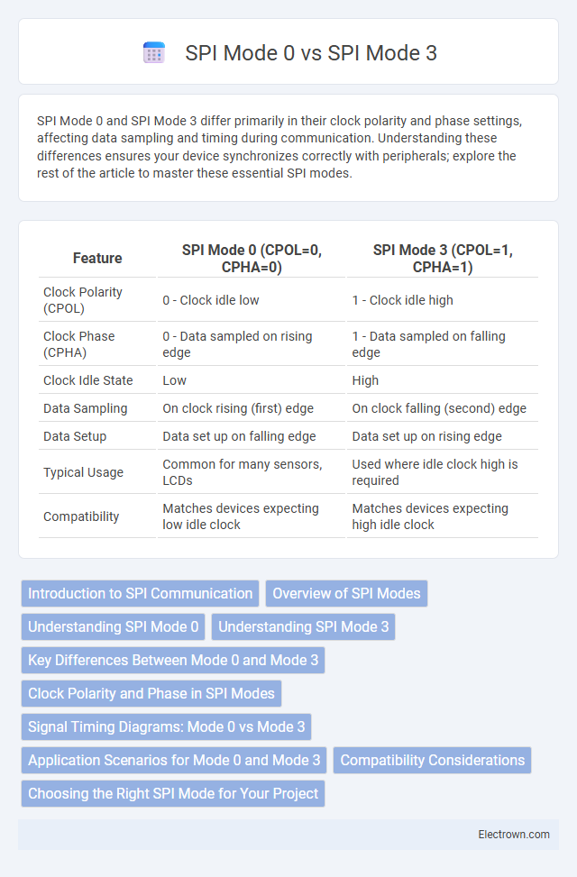
| Feature | SPI Mode 0 (CPOL=0, CPHA=0) | SPI Mode 3 (CPOL=1, CPHA=1) |
|---|---|---|
| Clock Polarity (CPOL) | 0 - Clock idle low | 1 - Clock idle high |
| Clock Phase (CPHA) | 0 - Data sampled on rising edge | 1 - Data sampled on falling edge |
| Clock Idle State | Low | High |
| Data Sampling | On clock rising (first) edge | On clock falling (second) edge |
| Data Setup | Data set up on falling edge | Data set up on rising edge |
| Typical Usage | Common for many sensors, LCDs | Used where idle clock high is required |
| Compatibility | Matches devices expecting low idle clock | Matches devices expecting high idle clock |
Introduction to SPI Communication
SPI Mode 0 and SPI Mode 3 define the clock polarity (CPOL) and clock phase (CPHA) settings critical for synchronization in SPI communication. Mode 0 uses CPOL=0 and CPHA=0 where data is sampled on the rising edge and shifted out on the falling edge, while Mode 3 sets CPOL=1 and CPHA=1, sampling data on the falling edge and shifting on the rising edge. Understanding the differences in these modes ensures your SPI devices communicate reliably by aligning clock signals with data transmission accurately.
Overview of SPI Modes
SPI Mode 0 operates with clock polarity (CPOL) set to 0 and clock phase (CPHA) set to 0, meaning data is sampled on the rising edge of the clock and data is shifted out on the falling edge. SPI Mode 3 features CPOL set to 1 and CPHA set to 1, so data is sampled on the falling edge and shifted out on the rising edge, which can help reduce noise in some applications. Understanding the differences between SPI Mode 0 and Mode 3 is essential for ensuring proper communication timing and data integrity in your SPI device or microcontroller setup.
Understanding SPI Mode 0
SPI Mode 0 configures the clock polarity (CPOL) to 0 and clock phase (CPHA) to 0, meaning the clock idle state is low and data is sampled on the rising edge. This mode is widely used in communication where data is captured on the clock's leading edge and shifted out on the trailing edge, ensuring reliable synchronization. Understanding SPI Mode 0 helps you design interfaces that require precise timing alignment between master and slave devices.
Understanding SPI Mode 3
SPI Mode 3 operates with clock polarity (CPOL) set to 1 and clock phase (CPHA) set to 1, meaning the clock idles high and data is sampled on the falling edge of the clock. Understanding SPI Mode 3 is crucial for ensuring compatibility between your master and slave devices, as mismatched modes can cause data corruption or communication failure. Compared to SPI Mode 0, which idles the clock low and samples on the rising edge, Mode 3 reverses both polarity and phase, impacting timing and signal interpretation in serial communication.
Key Differences Between Mode 0 and Mode 3
SPI Mode 0 and SPI Mode 3 differ primarily in clock polarity (CPOL) and clock phase (CPHA) settings: Mode 0 uses CPOL=0 and CPHA=0, meaning the clock idles low and data is sampled on the rising edge, while Mode 3 uses CPOL=1 and CPHA=1, causing the clock to idle high and data to be sampled on the falling edge. This distinction affects how data is transmitted and received, impacting timing and signal stability depending on your hardware requirements. Choosing the correct SPI mode ensures optimal communication and prevents data corruption in your device interfaces.
Clock Polarity and Phase in SPI Modes
SPI Mode 0 operates with a clock polarity (CPOL) of 0 and a clock phase (CPHA) of 0, meaning the clock idle state is low, and data is sampled on the rising edge of the clock. SPI Mode 3 uses CPOL = 1 and CPHA = 1, where the clock idle state is high, and data is captured on the falling edge of the clock. Understanding these differences in clock polarity and phase helps ensure your SPI communication aligns correctly with the device's timing requirements for reliable data transfer.
Signal Timing Diagrams: Mode 0 vs Mode 3
SPI Mode 0 operates with clock polarity (CPOL) = 0 and clock phase (CPHA) = 0, meaning data is sampled on the rising edge of the clock and shifted out on the falling edge, resulting in a specific timing diagram where the clock idles low. In contrast, SPI Mode 3 uses CPOL = 1 and CPHA = 1, causing data to be sampled on the falling edge and shifted out on the rising edge, with the clock idling high, which changes the alignment of signals in the timing diagram. Understanding these distinctions in signal timing diagrams helps you optimize communication protocols for reliable data exchange in embedded systems.
Application Scenarios for Mode 0 and Mode 3
SPI Mode 0 (CPOL=0, CPHA=0) is commonly used in applications requiring fast data sampling on the rising clock edge, such as sensors and memory devices where timing precision is critical. SPI Mode 3 (CPOL=1, CPHA=1) suits environments with noisy signals or slower devices, offering improved data stability by sampling on the falling clock edge. Your choice between Mode 0 and Mode 3 depends on device compatibility and signal integrity requirements in your specific application.
Compatibility Considerations
SPI Mode 0 operates with Clock Polarity (CPOL) = 0 and Clock Phase (CPHA) = 0, while SPI Mode 3 uses CPOL = 1 and CPHA = 1, leading to differences in clock signal behavior. Compatibility between devices requires matching SPI modes to ensure correct data sampling and clock alignment; mismatched modes can cause data corruption or communication failure. When integrating peripherals, verifying the SPI mode settings on both master and slave devices is critical for reliable operation.
Choosing the Right SPI Mode for Your Project
SPI Mode 0 and SPI Mode 3 differ primarily in clock polarity (CPOL) and clock phase (CPHA), with Mode 0 using CPOL=0 and CPHA=0, and Mode 3 using CPOL=1 and CPHA=1. Selecting the appropriate SPI mode depends on the specific requirements and compatibility of the peripherals in your project, as mismatched modes can lead to communication errors and data corruption. Understanding your device's datasheet and testing both modes during development ensures reliable and efficient data transmission.
SPI Mode 0 vs SPI Mode 3 Infographic