Bridgeless PFC offers higher efficiency and reduced conduction losses compared to Traditional PFC, resulting in improved power quality and lower energy consumption. Explore the rest of the article to understand how Bridgeless PFC can enhance Your power factor correction solutions.
Table of Comparison
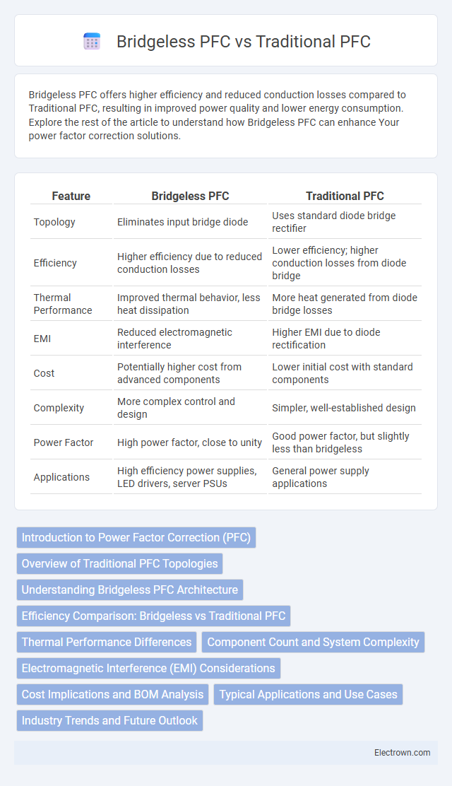
| Feature | Bridgeless PFC | Traditional PFC |
|---|---|---|
| Topology | Eliminates input bridge diode | Uses standard diode bridge rectifier |
| Efficiency | Higher efficiency due to reduced conduction losses | Lower efficiency; higher conduction losses from diode bridge |
| Thermal Performance | Improved thermal behavior, less heat dissipation | More heat generated from diode bridge losses |
| EMI | Reduced electromagnetic interference | Higher EMI due to diode rectification |
| Cost | Potentially higher cost from advanced components | Lower initial cost with standard components |
| Complexity | More complex control and design | Simpler, well-established design |
| Power Factor | High power factor, close to unity | Good power factor, but slightly less than bridgeless |
| Applications | High efficiency power supplies, LED drivers, server PSUs | General power supply applications |
Introduction to Power Factor Correction (PFC)
Power Factor Correction (PFC) improves the efficiency of electrical power usage by reducing reactive power and aligning voltage with current waveforms. Traditional PFC circuits often use a diode bridge rectifier followed by inductors and capacitors to achieve a near-unity power factor. Bridgeless PFC designs eliminate the diode bridge, reducing conduction losses and increasing efficiency, making them suitable for high-power applications requiring improved energy savings and thermal management.
Overview of Traditional PFC Topologies
Traditional PFC topologies primarily utilize the full-bridge diode rectifier combined with a boost converter to shape the input current and improve power factor. These designs rely on passive components and active switches controlled to maintain continuous conduction mode, ensuring compliance with IEC standards for harmonic distortion. Your choice of traditional PFC impacts system efficiency, electromagnetic interference, and overall complexity in power electronics.
Understanding Bridgeless PFC Architecture
Bridgeless PFC architecture eliminates the conventional diode bridge, reducing conduction losses and improving overall efficiency in power factor correction circuits. This design features fewer semiconductor components, resulting in lower power dissipation and better thermal performance compared to traditional PFC systems. Understanding your application's power requirements helps determine if bridgeless PFC offers enhanced efficiency and cost benefits over standard configurations.
Efficiency Comparison: Bridgeless vs Traditional PFC
Bridgeless PFC designs achieve higher efficiency than traditional PFC circuits by eliminating the diode bridge, which reduces conduction losses and heat generation. This improvement typically results in efficiency gains of 2-5% depending on load conditions, enhancing power factor and reducing energy waste. Your power systems benefit from lower energy costs and improved thermal management with bridgeless PFC technology.
Thermal Performance Differences
Bridgeless PFC circuits exhibit significantly improved thermal performance compared to traditional PFC designs by reducing conduction losses and minimizing heat generation within the power components. The elimination of the diode bridge rectifier lowers the power dissipation in MOSFETs, enabling more efficient heat distribution and smaller cooling requirements. Consequently, bridgeless PFC systems achieve higher efficiency and enhanced reliability under high power and temperature conditions.
Component Count and System Complexity
Bridgeless Power Factor Correction (PFC) circuits typically feature a reduced component count compared to Traditional PFC designs by eliminating the input bridge rectifier, which results in fewer semiconductor devices and associated passive components. This reduction directly lowers system complexity, simplifying PCB layout and improving reliability by minimizing points of failure and thermal hotspots. Consequently, Bridgeless PFC systems offer enhanced efficiency and compactness, making them preferable for applications requiring streamlined power conversion and improved power factor performance.
Electromagnetic Interference (EMI) Considerations
Bridgeless PFC circuits significantly reduce electromagnetic interference (EMI) compared to traditional PFC designs by minimizing diode conduction losses and eliminating the input bridge diode, which decreases high-frequency switching noise. The absence of the input bridge in bridgeless PFC allows for lower voltage stress components, resulting in improved electromagnetic compatibility (EMC) and easier EMI filter design. Traditional PFCs often require bulkier EMI filtering to mitigate noise generated by the full bridge rectifier's switching transitions.
Cost Implications and BOM Analysis
Bridgeless PFC circuits reduce cost implications by minimizing the number of semiconductor components, leading to a simpler Bill of Materials (BOM) compared to traditional PFC designs that rely on full-bridge rectifiers. The elimination of the bridge diode stage in Bridgeless PFC lowers conduction losses and thermal management requirements, resulting in decreased material and manufacturing costs. Detailed BOM analysis shows that Bridgeless PFCs offer improved efficiency and cost savings due to fewer discrete components and reduced complexity in power factor correction implementations.
Typical Applications and Use Cases
Bridgeless PFC circuits are commonly used in high-power LED lighting, server power supplies, and electric vehicle chargers due to their higher efficiency and reduced thermal stress compared to traditional PFC designs. Traditional PFC systems remain prevalent in consumer electronics, industrial machinery, and household appliances where cost-effectiveness and proven reliability are priorities. Bridgeless PFC technology suits applications demanding improved power density and lower electromagnetic interference, making it ideal for modern, energy-efficient devices.
Industry Trends and Future Outlook
Bridgeless PFC circuits are gaining traction in the power electronics industry due to their higher efficiency, reduced thermal stress, and smaller size compared to traditional PFC designs. As energy regulations tighten globally, manufacturers increasingly prefer bridgeless topologies for applications demanding improved power quality and lower harmonic distortion. You can expect ongoing innovation in semiconductor technologies and digital control methods to further enhance bridgeless PFC performance, shaping the future of sustainable power conversion solutions.
Bridgeless PFC vs Traditional PFC Infographic