E-plane Tee and H-plane Tee are fundamental microwave components used for signal splitting and combining in waveguide systems, with the E-plane Tee dividing signals along the electric field plane and the H-plane Tee doing so along the magnetic field plane, affecting their coupling characteristics and applications. Understanding the differences and operational principles of these tees can enhance your ability to design efficient RF and microwave circuits; read on to explore their unique features and uses in detail.
Table of Comparison
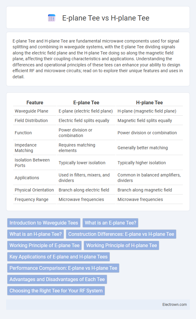
| Feature | E-plane Tee | H-plane Tee |
|---|---|---|
| Waveguide Plane | E-plane (electric field plane) | H-plane (magnetic field plane) |
| Field Distribution | Electric field splits equally | Magnetic field splits equally |
| Function | Power division or combination | Power division or combination |
| Impedance Matching | Requires matching elements | Generally better matching |
| Isolation Between Ports | Typically lower isolation | Typically higher isolation |
| Applications | Used in filters, mixers, and dividers | Common in balanced amplifiers, dividers |
| Physical Orientation | Branch along electric field | Branch along magnetic field |
| Frequency Range | Microwave frequencies | Microwave frequencies |
Introduction to Waveguide Tees
Waveguide tees are key components in microwave engineering used to split or combine signals. An E-plane tee, also known as the colinear tee, directs signals along the electric field plane, offering high isolation between ports with minimal signal loss. In contrast, the H-plane tee operates along the magnetic field plane and is favored for its balanced power division and consistent phase performance in waveguide networks.
What is an E-plane Tee?
An E-plane Tee is a waveguide T-junction where the branching occurs along the electric field plane, commonly used in microwave circuits for signal splitting or combining. It offers distinct impedance and phase characteristics compared to an H-plane Tee, which branches along the magnetic field plane. Your choice between these depends on the specific signal distribution and phase requirements of your RF system design.
What is an H-plane Tee?
An H-plane Tee is a microwave waveguide junction used to split or combine signals along the magnetic field plane, known as the H-plane. It features three ports arranged such that the wave propagation direction aligns with the magnetic field vector, enabling efficient power division or combination with minimal signal reflection. Unlike the E-plane Tee that operates on the electric field plane, the H-plane Tee is preferred in applications requiring high isolation between output ports and reduced cross-polarization effects.
Construction Differences: E-plane vs H-plane Tee
E-plane Tees are constructed by joining waveguides along the electric field (E-field) plane, resulting in a configuration that splits or combines signals with minimal phase difference and better isolation at higher frequencies. H-plane Tees, on the other hand, connect waveguides along the magnetic field (H-field) plane, designed for equal power splitting with different impedance characteristics and typically lower power handling compared to E-plane Tees. The structural orientation of E-plane Tees allows for compact bends and tighter coupling, whereas H-plane Tees offer simpler layouts with broader bandwidth but increased insertion loss.
Working Principle of E-plane Tee
The E-plane Tee operates by splitting or combining signals based on the electric field orientation, directing power flow along the electric field plane with minimal phase difference between outputs. It functions as a three-port waveguide junction where the input signal at the E-plane arm divides equally into the two colinear ports, maintaining signal integrity and isolation. This configuration is essential for applications requiring power division or combination while controlling polarization and phase relationships in microwave circuits.
Working Principle of H-plane Tee
The H-plane Tee operates by dividing the input signal into two outputs with equal phase and amplitude, utilizing the magnetic field distribution parallel to the H-plane of the waveguide. Its design ensures that the signals in the outputs maintain phase coherence, crucial for applications like balanced mixers and power dividers. The H-plane Tee's working principle relies on the magnetic coupling within the waveguide, optimizing energy transfer and minimizing insertion loss.
Key Applications of E-plane and H-plane Tees
E-plane tees are primarily used in applications requiring power division or combination in waveguide circuits where equal phase output is needed, such as in radar systems and antenna feed networks. H-plane tees excel in scenarios demanding signal routing with minimal phase difference and high isolation, commonly found in balanced mixers and phase shifters. Understanding your system's phase and isolation requirements will help determine whether an E-plane or H-plane tee best suits your design needs.
Performance Comparison: E-plane vs H-plane Tee
E-plane tees exhibit superior performance in high-frequency applications due to their ability to handle higher power levels and maintain better isolation between ports, making them ideal for signal distribution with minimal loss. H-plane tees offer enhanced bandwidth and impedance matching capabilities, providing more consistent amplitude and phase balance across a wider frequency range. The choice between E-plane and H-plane tees depends on specific system requirements such as power handling, frequency range, and isolation preferences, with E-plane tees favored for isolation and power and H-plane tees for bandwidth and matching stability.
Advantages and Disadvantages of Each Tee
An E-plane Tee offers compact size and simple design, making it ideal for applications requiring tight integration, but it suffers from higher insertion loss and reduced isolation compared to H-plane Tees. H-plane Tee provides better power handling and improved isolation, suitable for high-frequency and high-power systems, yet its larger size and more complex design may limit use in space-constrained setups. Understanding these trade-offs helps you select the right Tee for your microwave circuit's performance and size requirements.
Choosing the Right Tee for Your RF System
Selecting the right tee for your RF system depends on the specific signal distribution needs, with E-plane tees providing isolation and power splitting along the electric field plane, ideal for maintaining signal integrity in certain waveguide configurations. H-plane tees split signals along the magnetic field plane and are preferred when phase matching and power division across the magnetic field are critical. Your choice influences system performance, insertion loss, and isolation, making it essential to match the tee type to your waveguide orientation and application frequency.
E-plane Tee vs H-plane Tee Infographic