Edge-coupled and broadside-coupled configurations differ primarily in their electric and magnetic field interactions, affecting signal integrity, crosstalk, and bandwidth performance in high-frequency circuits. Understanding these differences will help you optimize your design for specific applications, so keep reading to explore their advantages and trade-offs.
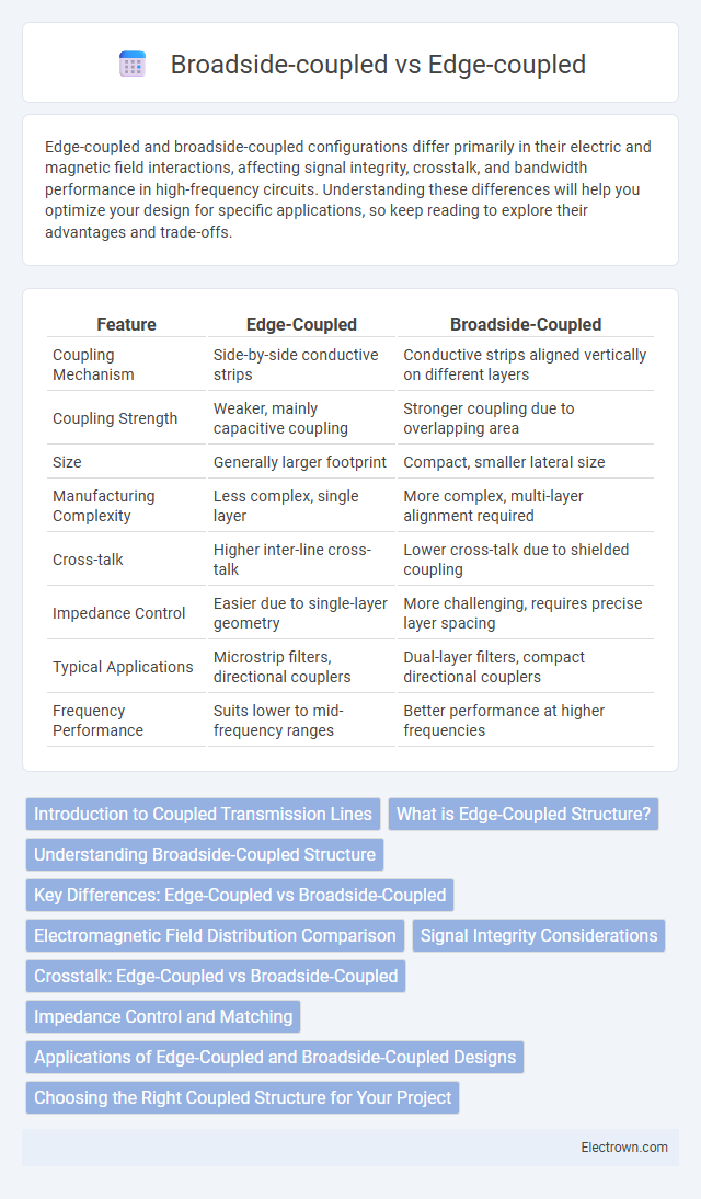
Table of Comparison
| Feature | Edge-Coupled | Broadside-Coupled |
|---|---|---|
| Coupling Mechanism | Side-by-side conductive strips | Conductive strips aligned vertically on different layers |
| Coupling Strength | Weaker, mainly capacitive coupling | Stronger coupling due to overlapping area |
| Size | Generally larger footprint | Compact, smaller lateral size |
| Manufacturing Complexity | Less complex, single layer | More complex, multi-layer alignment required |
| Cross-talk | Higher inter-line cross-talk | Lower cross-talk due to shielded coupling |
| Impedance Control | Easier due to single-layer geometry | More challenging, requires precise layer spacing |
| Typical Applications | Microstrip filters, directional couplers | Dual-layer filters, compact directional couplers |
| Frequency Performance | Suits lower to mid-frequency ranges | Better performance at higher frequencies |
Introduction to Coupled Transmission Lines
Coupled transmission lines are essential in high-frequency circuit design, utilizing two conductors placed near each other to achieve controlled electromagnetic coupling. Edge-coupled lines share adjacent edges, making them ideal for tight coupling with easier fabrication, while broadside-coupled lines align conductors parallel on opposite sides, offering stronger coupling and better isolation. Understanding these configurations improves your ability to optimize signal integrity and reduce crosstalk in RF and microwave applications.
What is Edge-Coupled Structure?
Edge-coupled structure is a type of transmission line configuration where two conductive strips are placed side by side with a narrow gap, creating strong capacitive and inductive coupling along their edges. This structure is commonly used in microwave circuits for its ease of fabrication and ability to achieve tight coupling coefficients, typically ranging from 0.1 to 0.9. Edge-coupled lines offer lower parasitic capacitance compared to broadside-coupled lines, making them suitable for high-frequency applications like filters, couplers, and phase shifters.
Understanding Broadside-Coupled Structure
Broadside-coupled structures feature two conductive traces placed directly on opposite sides of a dielectric substrate, resulting in strong capacitive coupling and reduced electromagnetic radiation compared to edge-coupled pairs. This configuration offers higher coupling coefficients and improved isolation, making it ideal for filters, directional couplers, and hybrid circuits in microwave engineering. Optimizing substrate thickness and dielectric constant enhances performance by controlling the effective permittivity and coupling strength in the broadside-coupled design.
Key Differences: Edge-Coupled vs Broadside-Coupled
Edge-coupled and broadside-coupled transmission lines differ primarily in their coupling orientation and electromagnetic field distribution, with edge-coupled lines having conductive edges adjacent to each other, resulting in weaker coupling and lower parasitic capacitance. Broadside-coupled lines feature overlapping conductors on different layers, providing stronger coupling, higher capacitance, and improved noise immunity for high-frequency signal integrity. Choosing between these configurations influences your design's impedance control, signal crosstalk, and overall electromagnetic compatibility in RF and microwave circuits.
Electromagnetic Field Distribution Comparison
Edge-coupled microstrip lines exhibit electromagnetic fields concentrated primarily at the edges of the conductors, leading to stronger fringing fields and higher coupling capacitance. Broadside-coupled lines feature electromagnetic fields distributed between the overlapping conductor surfaces, resulting in enhanced coupling due to increased capacitance and tighter field confinement. This field distribution difference directly impacts signal integrity and crosstalk characteristics in high-frequency circuit designs.
Signal Integrity Considerations
Edge-coupled and broadside-coupled configurations exhibit distinct signal integrity characteristics critical for high-speed PCB design. Edge-coupled pairs typically offer tighter control over differential impedance and lower crosstalk due to close conductor spacing, enhancing noise immunity in differential signaling. Broadside-coupled pairs, with conductors placed on adjacent layers, increase coupling capacitance and reduce loop area, which can improve electromagnetic compatibility but may introduce more complex impedance control challenges affecting signal rise times.
Crosstalk: Edge-Coupled vs Broadside-Coupled
Edge-coupled configurations typically exhibit higher crosstalk levels due to the closer proximity of signal edges, which increases electromagnetic interference between adjacent lines. In contrast, broadside-coupled arrangements, where conductors are stacked vertically with a dielectric layer in between, provide better isolation and significantly reduce crosstalk by minimizing capacitive coupling. Understanding these differences helps optimize your PCB design for signal integrity and noise reduction in high-speed circuits.
Impedance Control and Matching
Edge-coupled and broadside-coupled transmission lines differ significantly in impedance control and matching capabilities. Edge-coupled lines offer tighter impedance control due to their proximity affecting the electric field distribution, making them ideal for fine-tuning your circuit's characteristic impedance. Broadside-coupled lines provide higher coupling capacitance and better isolation, which can enhance impedance matching in multilayer PCB designs where minimizing crosstalk and achieving consistent impedance is crucial.
Applications of Edge-Coupled and Broadside-Coupled Designs
Edge-coupled designs are widely used in applications requiring tight coupling and compact layouts, such as differential signaling in high-speed communication systems and microwave filters. Broadside-coupled structures are preferred in scenarios demanding higher coupling coefficients and reduced radiation losses, making them ideal for broadband transformers and high-performance RF circuits. Your choice between edge-coupled and broadside-coupled designs will significantly impact the effectiveness of components in systems like phase shifters and couplers.
Choosing the Right Coupled Structure for Your Project
Edge-coupled and broadside-coupled structures differ primarily in their electric field distribution and coupling strength, with edge-coupled lines offering lower coupling and easier manufacturability, while broadside-coupled lines provide stronger coupling and reduced electromagnetic interference. Your project requirements for signal integrity, bandwidth, and available PCB space determine the optimal choice, as edge-coupled configurations suit high-frequency, tightly spaced layouts and broadside-coupled structures excel in applications demanding higher isolation and compact line configurations. Evaluating these factors ensures that the selected coupled structure achieves reliable performance and meets design specifications.
Edge-coupled vs broadside-coupled Infographic