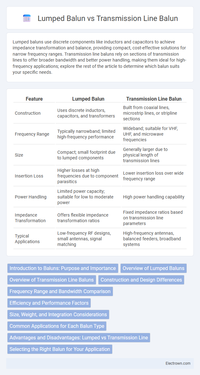
Lumped baluns use discrete components like inductors and capacitors to achieve impedance transformation and balance, providing compact, cost-effective solutions for narrow frequency ranges. Transmission line baluns rely on sections of transmission lines to offer broader bandwidth and better power handling, making them ideal for high-frequency applications; explore the rest of the article to determine which balun suits your specific needs.
Table of Comparison
| Feature | Lumped Balun | Transmission Line Balun |
|---|---|---|
| Construction | Uses discrete inductors, capacitors, and transformers | Built from coaxial lines, microstrip lines, or stripline sections |
| Frequency Range | Typically narrowband; limited high-frequency performance | Wideband; suitable for VHF, UHF, and microwave frequencies |
| Size | Compact; small footprint due to lumped components | Generally larger due to physical length of transmission lines |
| Insertion Loss | Higher losses at high frequencies due to component parasitics | Lower insertion loss over wide frequency range |
| Power Handling | Limited power capacity; suitable for low to moderate power | High power handling capability |
| Impedance Transformation | Offers flexible impedance transformation ratios | Fixed impedance ratios based on transmission line parameters |
| Typical Applications | Low-frequency RF designs, small antennas, signal matching | High-frequency antennas, balanced feeders, broadband systems |
Introduction to Baluns: Purpose and Importance
Baluns serve as essential components in RF systems, enabling the conversion between balanced and unbalanced signals to ensure impedance matching and minimize signal reflection. Lumped baluns utilize discrete inductors and capacitors to achieve compact size and effective operation at lower frequencies, whereas transmission line baluns employ distributed transmission lines for broader bandwidth and superior power handling. Understanding the purpose and functional differences of lumped versus transmission line baluns is critical for optimizing system performance in antennas, mixers, and amplifiers.
Overview of Lumped Baluns
Lumped baluns consist of discrete inductors and capacitors arranged to match impedance and provide balanced output in RF circuits, offering compact size and ease of integration in PCB designs. Their design flexibility allows precise control over frequency response, making them suitable for narrowband applications where size and cost are critical factors. If you require efficient impedance transformation and phase inversion in a limited space, lumped baluns serve as an ideal choice compared to larger transmission line baluns.
Overview of Transmission Line Baluns
Transmission line baluns utilize transmission line segments, such as coaxial cables or strip lines, to achieve balanced-to-unbalanced signal transformation with minimal phase and amplitude imbalance. They provide wide bandwidth and excellent impedance matching, making them suitable for RF and microwave applications. The construction leverages the physical properties of transmission lines, ensuring stable performance over a broad frequency range compared to lumped component baluns.
Construction and Design Differences
Lumped baluns utilize discrete inductors and capacitors arranged in a compact network, making them ideal for low-frequency applications and space-constrained designs. Transmission line baluns rely on sections of transmission lines, such as coaxial cables or microstrip lines, to achieve impedance transformation and balance, offering superior performance at higher frequencies. Understanding these construction and design differences helps optimize Your RF circuit for efficiency and size requirements.
Frequency Range and Bandwidth Comparison
Lumped baluns typically operate effectively at lower frequencies, often below 300 MHz, due to their reliance on discrete components like inductors and capacitors, which limits bandwidth. Transmission line baluns, on the other hand, excel at higher frequencies and offer a broader bandwidth, sometimes spanning multiple octaves, making them ideal for wideband applications. Your choice depends on the frequency range of your project and the bandwidth requirements, with transmission line baluns better suited for high-frequency, wideband signals.
Efficiency and Performance Factors
Lumped baluns typically offer compact size and ease of integration but may suffer from higher insertion loss and limited bandwidth compared to transmission line baluns. Transmission line baluns provide superior efficiency with lower insertion loss and broader frequency performance due to their distributed element design. Your choice depends on the specific application requirements, balancing size constraints against performance needs such as power handling and signal integrity.
Size, Weight, and Integration Considerations
Lumped baluns offer a compact size and reduced weight due to their use of discrete inductors and capacitors, making them ideal for space-constrained and lightweight applications. Transmission line baluns, constructed from sections of transmission lines, tend to be larger and heavier but provide broader bandwidth and better power handling. Integration considerations favor lumped baluns in PCB designs where minimal footprint is crucial, while transmission line baluns suit systems requiring robust performance and where size and weight are less constrained.
Common Applications for Each Balun Type
Lumped baluns are commonly used in low-frequency applications such as HF radio antennas and small signal baluns due to their compact size and simplicity. Transmission line baluns are preferred in higher frequency applications like UHF and microwave systems, including cable TV and RF balanced to unbalanced signal conversion, where minimal insertion loss and wide bandwidth are critical. Each balun type serves distinct roles depending on frequency range, power handling, and physical size constraints in communication and antenna systems.
Advantages and Disadvantages: Lumped vs Transmission Line
Lumped baluns offer compact size and ease of integration into printed circuit boards, making them ideal for low-frequency applications where space is limited, but suffer from increased insertion loss and limited bandwidth compared to transmission line baluns. Transmission line baluns provide wide bandwidth, low insertion loss, and high power handling, suitable for high-frequency and RF applications, although they require more physical space and precise impedance matching. Your choice depends on balancing size constraints against performance needs, with lumped baluns favoring compact designs and transmission line baluns excelling in efficiency and frequency range.
Selecting the Right Balun for Your Application
Selecting the right balun depends on the specific frequency range, power handling, and physical size constraints of your application. Lumped baluns offer compact size and are ideal for low-frequency, narrowband uses, while transmission line baluns provide better performance at higher frequencies and broader bandwidths. Consider insertion loss, impedance matching, and environmental factors to optimize signal integrity in RF and microwave circuits.
Lumped Balun vs Transmission Line Balun Infographic