S-parameters describe how RF signals behave in terms of reflection and transmission at high frequencies, while Z-parameters focus on voltage and current relationships in linear electrical networks. Understanding these distinctions will enhance your grasp of network analysis; read on to explore the detailed differences between S-parameters and Z-parameters.
Table of Comparison
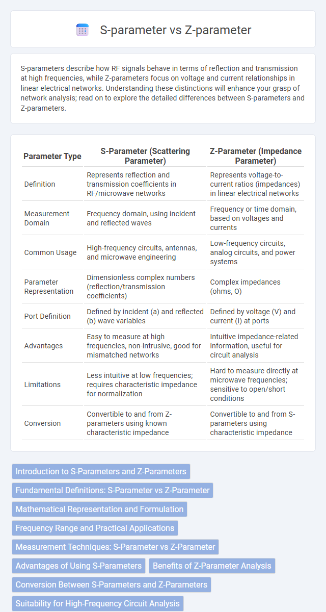
| Parameter Type | S-Parameter (Scattering Parameter) | Z-Parameter (Impedance Parameter) |
|---|---|---|
| Definition | Represents reflection and transmission coefficients in RF/microwave networks | Represents voltage-to-current ratios (impedances) in linear electrical networks |
| Measurement Domain | Frequency domain, using incident and reflected waves | Frequency or time domain, based on voltages and currents |
| Common Usage | High-frequency circuits, antennas, and microwave engineering | Low-frequency circuits, analog circuits, and power systems |
| Parameter Representation | Dimensionless complex numbers (reflection/transmission coefficients) | Complex impedances (ohms, O) |
| Port Definition | Defined by incident (a) and reflected (b) wave variables | Defined by voltage (V) and current (I) at ports |
| Advantages | Easy to measure at high frequencies, non-intrusive, good for mismatched networks | Intuitive impedance-related information, useful for circuit analysis |
| Limitations | Less intuitive at low frequencies; requires characteristic impedance for normalization | Hard to measure directly at microwave frequencies; sensitive to open/short conditions |
| Conversion | Convertible to and from Z-parameters using known characteristic impedance | Convertible to and from S-parameters using characteristic impedance |
Introduction to S-Parameters and Z-Parameters
S-parameters (scattering parameters) describe how radio frequency signals behave in a network, capturing reflection and transmission characteristics crucial in high-frequency circuit design. Z-parameters (impedance parameters) represent voltage-current relationships within a network, providing insights into the input and output impedances and mutual coupling between ports. Understanding both S-parameters and Z-parameters is essential for analyzing and designing your RF and microwave systems effectively.
Fundamental Definitions: S-Parameter vs Z-Parameter
S-parameters, or scattering parameters, represent how RF signals reflect and transmit through a network, essential for characterizing high-frequency circuits. Z-parameters, or impedance parameters, describe the voltage-current relationship in a network, crucial for analyzing linear circuits at low frequencies. Understanding these fundamental definitions helps you select the appropriate parameter set for accurate circuit modeling and measurement.
Mathematical Representation and Formulation
S-parameters describe network behavior in terms of incident and reflected waves, represented as a matrix relating outgoing to incoming wave amplitudes, typically expressed as \( \mathbf{b} = \mathbf{S} \mathbf{a} \). Z-parameters characterize linear electrical networks through voltages and currents at ports, formulated as \( \mathbf{V} = \mathbf{Z} \mathbf{I} \), where the impedance matrix \(\mathbf{Z}\) relates port voltages to currents. Both parameter sets provide equivalent network descriptions but differ in formulation; S-parameters use wave quantities suited for high-frequency applications, while Z-parameters rely on voltage-current relationships common in low-frequency circuit analysis.
Frequency Range and Practical Applications
S-parameters excel in high-frequency applications, typically from hundreds of MHz up to several GHz, making them ideal for microwave and RF circuit analysis such as antennas, amplifiers, and filters. Z-parameters are better suited for low-frequency ranges, usually below a few hundred MHz, and are often used in analyzing passive components like resistors, inductors, and transformers in circuit design. Your choice between S-parameters and Z-parameters depends on the operating frequency and the specific requirements of practical applications in signal integrity and network characterization.
Measurement Techniques: S-Parameter vs Z-Parameter
S-parameter measurement techniques utilize vector network analyzers to capture reflected and transmitted signals at high frequencies, making them ideal for RF and microwave circuits characterization. Z-parameter measurements involve applying known currents and measuring voltages, often requiring impedance analyzers or LCR meters, which are more common in low-frequency or linear circuit analysis. Understanding these techniques helps you select the appropriate method for accurate parameter extraction in your circuit design or testing process.
Advantages of Using S-Parameters
S-parameters offer significant advantages in high-frequency circuit analysis, especially for microwave and RF applications, by simplifying the measurement of complex networks without requiring open or short-circuit conditions. They provide direct insight into reflection and transmission characteristics, enabling accurate modeling of system behavior under real operating conditions. Your ability to easily cascade multiple two-port networks and analyze power flow makes S-parameters essential for practical design and testing.
Benefits of Z-Parameter Analysis
Z-parameter analysis offers distinct advantages for electrical circuit characterization by directly relating voltages and currents, which simplifies the design and analysis of multi-port networks, especially in low-frequency applications. Unlike S-parameters that focus on power wave reflections, Z-parameters provide intuitive impedance-based insights crucial for accurate modeling of passive network elements and impedance matching. This makes Z-parameters highly beneficial in identifying open-circuit conditions and straightforwardly cascading network sections in system-level analysis.
Conversion Between S-Parameters and Z-Parameters
Conversion between S-parameters and Z-parameters involves matrix transformations where S-parameters represent normalized wave quantities and Z-parameters represent voltages and currents. The formulas use the characteristic impedance \( Z_0 \) to relate the scattering matrix \( S \) to the impedance matrix \( Z \) through \( Z = Z_0 (I + S)(I - S)^{-1} \) and \( S = (Z - Z_0 I)(Z + Z_0 I)^{-1} \), with \( I \) being the identity matrix. This conversion is essential in RF and microwave engineering for analyzing network behavior under different measurement conditions.
Suitability for High-Frequency Circuit Analysis
S-parameters are highly suitable for high-frequency circuit analysis due to their ability to directly measure reflection and transmission coefficients at microwave and RF frequencies, simplifying the characterization of components like amplifiers and filters. Z-parameters, or impedance parameters, become less practical at high frequencies because parasitic inductances and capacitances distort impedance measurements, making them harder to interpret. Your high-frequency circuit designs benefit from using S-parameters, which offer more accurate and convenient data for network analysis and simulation.
Conclusion: Choosing Between S-Parameters and Z-Parameters
S-parameters excel in high-frequency RF and microwave circuit analysis due to their ease of measurement and reflection/transmission characterization. Z-parameters are more suitable for low-frequency or linear circuit modeling where impedance relationships are directly analyzed. You should choose S-parameters for network behavior at high frequencies and Z-parameters when dealing with impedance at lower frequencies or simpler network models.
S-parameter vs Z-parameter Infographic