Tapered transmission lines offer smooth impedance matching by gradually changing the line width, minimizing reflections over a broad frequency range, while stepped impedance transformers use discrete sections of transmission lines with different impedances to achieve impedance transformation in a simpler structure. Explore the rest of the article to understand which method suits your RF design needs best.
Table of Comparison
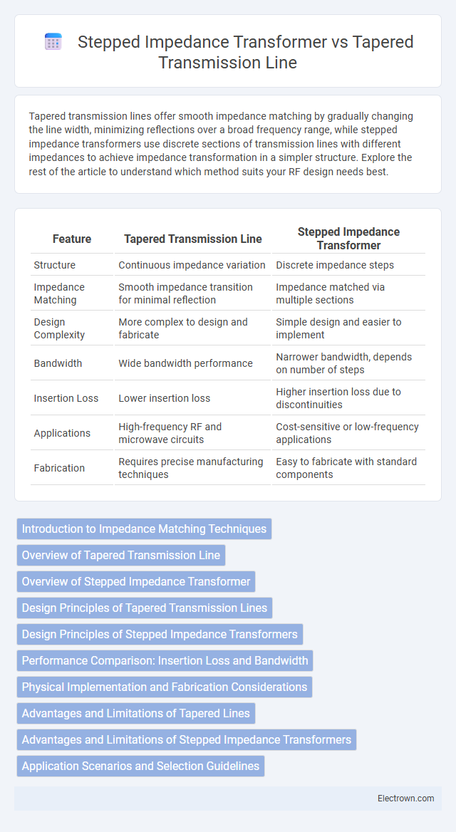
| Feature | Tapered Transmission Line | Stepped Impedance Transformer |
|---|---|---|
| Structure | Continuous impedance variation | Discrete impedance steps |
| Impedance Matching | Smooth impedance transition for minimal reflection | Impedance matched via multiple sections |
| Design Complexity | More complex to design and fabricate | Simple design and easier to implement |
| Bandwidth | Wide bandwidth performance | Narrower bandwidth, depends on number of steps |
| Insertion Loss | Lower insertion loss | Higher insertion loss due to discontinuities |
| Applications | High-frequency RF and microwave circuits | Cost-sensitive or low-frequency applications |
| Fabrication | Requires precise manufacturing techniques | Easy to fabricate with standard components |
Introduction to Impedance Matching Techniques
Tapered transmission lines and stepped impedance transformers are fundamental impedance matching techniques used to minimize signal reflection and maximize power transfer in RF circuits. Tapered transmission lines provide a continuous change in impedance along their length, offering broadband matching with low insertion loss. Stepped impedance transformers employ discrete sections with varying characteristic impedances, optimizing impedance matching over specific frequency bands and allowing you to tailor your circuit's performance precisely.
Overview of Tapered Transmission Line
Tapered transmission lines provide a smooth variation in impedance along their length, minimizing reflection loss and improving bandwidth in RF and microwave circuits. Their gradual impedance change offers superior impedance matching compared to stepped impedance transformers, which use discrete impedance sections to approximate the desired transformation. This continuous transition in tapered lines enhances signal integrity and reduces insertion loss, making them ideal for high-frequency applications.
Overview of Stepped Impedance Transformer
Stepped impedance transformers consist of multiple transmission line sections with varying characteristic impedances designed to match different impedance levels across a specific frequency range. Their discrete impedance steps create an approximate impedance transformation, offering a compact and simple structure ideal for narrowband applications. You can achieve precise impedance matching using carefully calculated segment lengths and impedances, providing effective power transfer in RF and microwave circuits.
Design Principles of Tapered Transmission Lines
Tapered transmission lines achieve impedance matching by gradually varying the characteristic impedance along the line length, minimizing reflection and signal loss. The design principles involve smooth impedance transitions typically realized through exponential, linear, or Klopfenstein tapers, optimizing bandwidth and return loss. Material selection, taper length, and impedance profile are critical factors that influence performance and effective power transfer in high-frequency circuits.
Design Principles of Stepped Impedance Transformers
Stepped impedance transformers use cascaded sections of transmission lines with alternating high and low characteristic impedances to achieve impedance matching by gradually transforming impedance over multiple discrete steps. The design principle relies on selecting the length of each section as a fraction of the operating wavelength, typically a quarter-wavelength, to create reactive cancellation and minimize reflection coefficients across the desired frequency band. By optimizing the number of steps and impedance ratios, designers balance bandwidth and physical size while ensuring efficient power transfer in RF and microwave circuits.
Performance Comparison: Insertion Loss and Bandwidth
Tapered transmission lines generally offer lower insertion loss due to their smooth impedance transition, which minimizes reflections and dissipation compared to stepped impedance transformers. The bandwidth of tapered lines is wider, as the gradual impedance variation supports broadband matching, whereas stepped impedance transformers exhibit narrower bandwidth limited by discrete impedance jumps. Performance optimization favors tapered lines for applications requiring minimal signal loss and broad frequency coverage.
Physical Implementation and Fabrication Considerations
Tapered transmission lines feature a continuous variation in characteristic impedance, offering smooth impedance matching but require precise control over conductor width or substrate properties during fabrication, which can be challenging for standard lithography processes. Stepped impedance transformers consist of discrete sections with uniform impedance values, simplifying physical implementation with standard PCB fabrication techniques yet potentially introducing reflection points at impedance discontinuities. Manufacturing tapered lines demands higher resolution patterning and more complex design tools, while stepped transformers benefit from modular designs and easier assembly but may require careful optimization of segment lengths to minimize insertion loss and maintain bandwidth.
Advantages and Limitations of Tapered Lines
Tapered transmission lines offer smoother impedance transitions with reduced reflection and broadband performance, making them ideal for applications requiring minimal signal distortion. Their continuous impedance variation provides greater design flexibility compared to stepped impedance transformers, which rely on abrupt changes that can cause increased insertion loss and limited bandwidth. However, tapered lines are typically more complex to fabricate and may require longer physical length, posing challenges in compact circuit designs.
Advantages and Limitations of Stepped Impedance Transformers
Stepped impedance transformers provide a simple and cost-effective method for impedance matching over narrow bandwidths by utilizing discrete transmission line sections with differing characteristic impedances. Their advantages include ease of design, compact size, and effective impedance transformation for specific frequencies; however, limitations arise from increased insertion loss, poor performance over wide bandwidths, and sensitivity to manufacturing tolerances. Your choice of a stepped impedance transformer must consider these trade-offs, especially when bandwidth and insertion loss are critical factors in RF and microwave circuits.
Application Scenarios and Selection Guidelines
Tapered transmission lines are ideal for broadband impedance matching in applications requiring smooth transition between impedances, such as wideband RF filters and antenna feed networks, due to their continuous impedance variation. Stepped impedance transformers are preferred in narrowband scenarios like microwave circuits and filter designs where discrete impedance sections optimize performance with simpler fabrication. Your choice depends on bandwidth requirements and fabrication tolerance, with tapered lines excelling in wideband environments and stepped transformers being more cost-effective for narrowband applications.
Tapered transmission line vs stepped impedance transformer Infographic