A cross-coupled inverter uses two inverters connected in a feedback loop, enabling bistable operation ideal for memory cells, whereas a simple inverter provides a basic voltage level inversion without feedback. Explore the rest of the article to understand how these differences impact your circuit design choices.
Table of Comparison
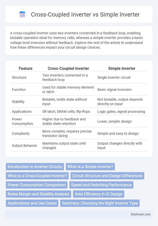
| Feature | Cross-Coupled Inverter | Simple Inverter |
|---|---|---|
| Structure | Two inverters connected in a feedback loop | Single inverter circuit |
| Function | Used for stable memory element or latch | Basic signal inversion |
| Stability | Bistable, holds state without input | Not bistable, output depends directly on input |
| Applications | SR latch, SRAM cells, flip-flops | Logic gates, signal processing |
| Power Consumption | Higher due to feedback and stable state retention | Lower, simpler design |
| Complexity | More complex, requires precise transistor sizing | Simple and easy to design |
| Output Behavior | Maintains output state until changed | Output changes directly with input |
Introduction to Inverter Circuits
Inverter circuits convert DC signals to AC signals, playing a vital role in digital electronics and power applications. Cross-coupled inverters feature two complementary transistors arranged in a feedback loop, enabling robust bistable operation and higher noise immunity compared to simple inverters, which consist of a single transistor switching device. Your choice between these inverters impacts circuit stability, switching speed, and power consumption depending on the application requirements.
What is a Simple Inverter?
A simple inverter is a basic electronic circuit that converts DC voltage into AC voltage, typically consisting of a single transistor or switch. It provides straightforward functionality with limited stability and switching efficiency compared to complex configurations. Your choice between a simple and cross-coupled inverter depends on the required output reliability and power performance in your application.
What is a Cross-Coupled Inverter?
A Cross-Coupled Inverter consists of two complementary MOSFET-based inverters connected in a feedback loop, creating a bistable circuit commonly used in SRAM cells and flip-flops for data storage. This design provides inherent positive feedback, enabling the circuit to maintain stable logic states and improving noise margins compared to a simple inverter. The cross-coupled topology also enhances speed and power efficiency by reducing switching noise and leakage currents.
Circuit Structure and Design Differences
Cross-coupled inverters consist of two inverters connected in a feedback loop, forming a bistable latch that maintains stable states and is commonly used in SRAM cells for data storage. Simple inverters have a single-stage structure with one PMOS and one NMOS transistor that invert the input signal without feedback, serving as a basic logic gate. The design difference lies in complexity and functionality: cross-coupled inverters enable memory functionality with feedback for state retention, while simple inverters perform straightforward signal inversion without state storage.
Power Consumption Comparison
Cross-coupled inverters generally consume less power compared to simple inverters due to their ability to maintain output states with reduced static current flow, which enhances energy efficiency in memory and latch circuits. Simple inverters exhibit higher power consumption as they rely on continuous current during switching transitions, leading to increased dynamic power dissipation. Your design can benefit from the lower power profile of cross-coupled inverters, especially in low-power applications requiring stable bistable operation.
Speed and Switching Performance
Cross-coupled inverters exhibit faster switching speeds and improved dynamic performance compared to simple inverters due to their positive feedback mechanism, which accelerates voltage transitions. This enhanced speed results in reduced propagation delay and increased switching frequency, making them ideal for applications requiring high-speed oscillators and latches. Simple inverters, while more straightforward and power-efficient, typically have slower switching times and limited ability to maintain stable states under rapid switching conditions.
Noise Margin and Stability Analysis
Cross-coupled inverters exhibit superior noise margins compared to simple inverters due to their regenerative feedback mechanism, which enhances signal integrity by reinforcing output states. Stability analysis reveals that cross-coupled configurations maintain bistable operation with robust state retention under voltage fluctuations, whereas simple inverters are prone to metastability and greater susceptibility to noise disturbances. The regenerative action in cross-coupled inverters ensures higher noise immunity and stable switching thresholds, critical for reliable digital circuit performance.
Area Efficiency in IC Design
Cross-coupled inverters generally consume more silicon area compared to simple inverters due to the duplicated transistor pairs required for feedback loops, which impacts area efficiency in IC design. Simple inverters use fewer transistors, resulting in a smaller footprint and improved density, beneficial for large-scale integration. Your choice between the two should consider trade-offs between functionality and silicon area constraints.
Applications and Use Cases
Cross-coupled inverters are commonly used in SRAM cells and flip-flops for stable memory storage due to their bistable latch properties. Simple inverters are widely applied in basic signal inversion tasks, oscillators, and digital logic circuits where single-stage signal inversion is needed. Cross-coupled configurations excel in applications requiring data retention and noise immunity, while simple inverters suit straightforward logic and timing functions.
Summary: Choosing the Right Inverter Type
Cross-coupled inverters offer higher noise margins and better stability, making them ideal for memory cells and oscillator circuits, whereas simple inverters excel in speed and lower power consumption for basic logic operations. Your choice depends on the application's requirements, with cross-coupled designs suited for complex, stable feedback loops and simple inverters preferable for fast, straightforward signal inversion. Evaluating factors like power efficiency, switching speed, and circuit complexity will help determine the right inverter type for your project.
Cross-coupled inverter vs simple inverter Infographic