A source follower provides high input impedance and low output impedance, making it ideal for voltage buffering, whereas a common emitter amplifier offers high voltage gain but lower input impedance, commonly used for signal amplification. Explore the rest of the article to understand which configuration suits Your electronic circuit needs best.
Table of Comparison
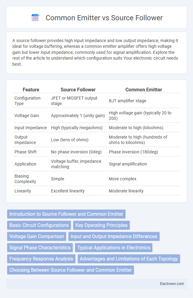
| Feature | Source Follower | Common Emitter |
|---|---|---|
| Configuration Type | JFET or MOSFET output stage | BJT amplifier stage |
| Voltage Gain | Approximately 1 (unity gain) | High voltage gain (typically 20 to 200) |
| Input Impedance | High (typically megaohms) | Moderate to high (kiloohms) |
| Output Impedance | Low (tens of ohms) | Moderate to high (hundreds of ohms to kiloohms) |
| Phase Shift | No phase inversion (0deg) | Phase inversion (180deg) |
| Application | Voltage buffer, impedance matching | Signal amplification |
| Biasing Complexity | Simple | More complex |
| Linearity | Excellent linearity | Moderate linearity |
Introduction to Source Follower and Common Emitter
Source followers and common emitters are fundamental transistor amplifier configurations used in analog circuits. A source follower, typically built with a MOSFET, provides high input impedance, low output impedance, and a voltage gain close to unity, making it ideal for buffering signals. In contrast, the common emitter configuration, based on BJTs, offers significant voltage gain and moderate input/output impedance, making it suitable for amplification tasks where signal boosting is required.
Basic Circuit Configurations
The source follower circuit is a type of field-effect transistor (FET) configuration where the output is taken from the source terminal, offering high input impedance and low output impedance, ideal for impedance matching. In contrast, the common emitter configuration uses a bipolar junction transistor (BJT) with the emitter as the common terminal, providing significant voltage gain and phase inversion between input and output signals. Both configurations serve different roles in amplifier design, with source followers preferred for buffer stages and common emitters used for voltage amplification.
Key Operating Principles
The source follower operates with the MOSFET's source as the output, providing a voltage gain close to unity and high input impedance, ideal for impedance matching and buffering. The common emitter uses a BJT with the emitter as common terminal, achieving significant voltage gain and phase inversion, making it suitable for amplifying weak signals. Both configurations rely on controlling the transistor's base or gate voltage to modulate current flow, but differ in input-output relationships and signal phase characteristics.
Voltage Gain Comparison
Source followers exhibit a voltage gain typically less than unity, often close to 1, making them ideal for impedance matching but not signal amplification. Common emitter configurations provide significant voltage gain, often ranging from 20 to 100 or more, depending on transistor parameters and load resistance. The voltage gain in common emitter amplifiers results from the transistor's transconductance and collector load, contrasting the source follower's gain limited by the MOSFET's source degeneration.
Input and Output Impedance Differences
The source follower configuration exhibits high input impedance due to the gate terminal's voltage-controlled behavior and low output impedance, making it ideal for impedance buffering. In contrast, the common emitter amplifier presents moderate input impedance at the base and higher output impedance at the collector, suitable for voltage gain applications but less effective as a buffer. These impedance characteristics influence their usage in circuit design, with the source follower preferred for impedance matching and the common emitter chosen for signal amplification.
Signal Phase Characteristics
A source follower provides an output signal that is in phase with the input, making it ideal for buffering and impedance matching without phase inversion. In contrast, a common emitter amplifier produces an output signal that is 180 degrees out of phase with the input, which can be advantageous for signal inversion in certain analog circuits. Understanding the phase relationship in these configurations helps you choose the right topology for your signal processing needs.
Typical Applications in Electronics
Source followers are typically used in voltage buffering and impedance matching applications due to their high input impedance and low output impedance, making them ideal for signal conditioning in audio and RF circuits. Common emitter configurations excel in amplification tasks, providing significant voltage gain and phase inversion, which is essential in analog amplifiers and switching circuits. Your choice between these configurations should consider whether voltage gain or signal buffering is the primary requirement in your electronic design.
Frequency Response Analysis
Frequency response analysis reveals the source follower offers higher bandwidth and improved high-frequency performance due to its low output impedance, minimizing signal attenuation. The common emitter stage, while providing higher voltage gain, tends to suffer from reduced bandwidth and phase shifts caused by Miller capacitance effects. Designing your circuit with a source follower can enhance frequency response in applications demanding fast signal switching and stable gain at higher frequencies.
Advantages and Limitations of Each Topology
Source follower topology offers high input impedance and low output impedance, making it ideal for impedance matching and buffer stages; however, it has a voltage gain slightly less than unity and limited voltage swing. Common emitter configuration provides significant voltage gain and phase inversion, suitable for amplification applications, but exhibits moderate input impedance and higher output impedance, affecting loading effects. The source follower excels in linearity and low distortion, while the common emitter benefits from stronger gain but with more signal distortion and potential thermal instability.
Choosing Between Source Follower and Common Emitter
Choosing between a source follower and a common emitter amplifier depends on your application's voltage gain and impedance requirements. A source follower offers unity voltage gain with high input impedance and low output impedance, ideal for impedance matching and signal buffering. In contrast, the common emitter configuration provides high voltage gain but lower input impedance, making it suitable for amplifying weak signals in circuits where gain is a priority.
Source follower vs Common emitter Infographic