Source-coupled pairs offer high input impedance and low flicker noise, making them suitable for low-noise applications, whereas emitter-coupled pairs provide better linearity and higher gain, often preferred in analog signal processing. Explore the rest of the article to understand which transistor pair best suits Your circuit design needs.
Table of Comparison
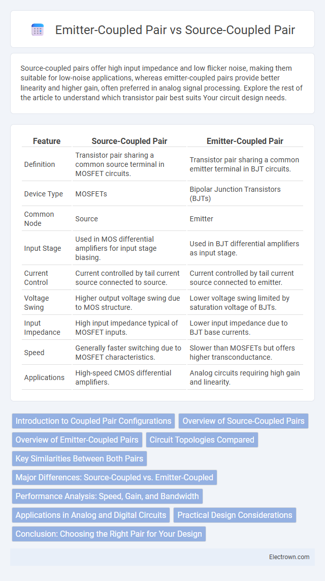
| Feature | Source-Coupled Pair | Emitter-Coupled Pair |
|---|---|---|
| Definition | Transistor pair sharing a common source terminal in MOSFET circuits. | Transistor pair sharing a common emitter terminal in BJT circuits. |
| Device Type | MOSFETs | Bipolar Junction Transistors (BJTs) |
| Common Node | Source | Emitter |
| Input Stage | Used in MOS differential amplifiers for input stage biasing. | Used in BJT differential amplifiers as input stage. |
| Current Control | Current controlled by tail current source connected to source. | Current controlled by tail current source connected to emitter. |
| Voltage Swing | Higher output voltage swing due to MOS structure. | Lower voltage swing limited by saturation voltage of BJTs. |
| Input Impedance | High input impedance typical of MOSFET inputs. | Lower input impedance due to BJT base currents. |
| Speed | Generally faster switching due to MOSFET characteristics. | Slower than MOSFETs but offers higher transconductance. |
| Applications | High-speed CMOS differential amplifiers. | Analog circuits requiring high gain and linearity. |
Introduction to Coupled Pair Configurations
Source-coupled pairs use MOSFETs where the sources are connected together to form a current mirror or differential pair, maximizing input impedance and speed in CMOS circuits. Emitter-coupled pairs, typically implemented with BJTs, connect emitters together for differential signaling, offering high gain and low offset voltage suitable for analog applications. Both configurations serve as fundamental building blocks in analog design, enabling precise differential amplification and current steering.
Overview of Source-Coupled Pairs
Source-coupled pairs, also known as current mirrors or transistor pairs with a common source node, operate by sharing a constant current source at the source terminals, enabling high input impedance and improved voltage gain in analog circuits. These pairs are widely used in differential amplifier stages to achieve better linearity and reduced noise compared to emitter-coupled pairs, which share a common emitter node. The source-coupled configuration is favored in CMOS technology for its superior matching characteristics and power efficiency in integrated circuit design.
Overview of Emitter-Coupled Pairs
Emitter-coupled pairs (ECPs) are fundamental differential amplifier stages widely used in analog integrated circuits for their high gain and linearity. They function by coupling two bipolar junction transistors at their emitters, enabling efficient current steering and improved common-mode rejection ratio (CMRR). ECPs offer faster switching speeds and lower voltage operation compared to source-coupled pairs, making them ideal for high-frequency and precision applications.
Circuit Topologies Compared
Source-coupled pairs use MOSFETs with sources tied together and connected to a current source, offering high input impedance and low noise ideal for high-frequency analog circuits. Emitter-coupled pairs employ BJTs with emitters connected to a current source, providing better transconductance and faster switching speeds suited for low-voltage, high-speed applications. Your choice between these circuit topologies depends on factors such as device type, required input impedance, noise performance, and operating frequency range.
Key Similarities Between Both Pairs
Source-coupled pairs and emitter-coupled pairs both function as differential amplifiers, providing high gain and improved linearity by amplifying the difference between two input signals. Both configurations rely on transistor pairs and use a constant current source to achieve high common-mode rejection ratio (CMRR) and reduce noise interference. Your choice between them depends on the required input stage type--MOSFETs for source-coupled and BJTs for emitter-coupled--yet both share core principles of differential amplification and current control.
Major Differences: Source-Coupled vs. Emitter-Coupled
Source-coupled pairs use MOSFETs with current sources at the source terminals, offering higher input impedance and better frequency response compared to emitter-coupled pairs, which utilize BJTs with current sources at the emitters. Emitter-coupled pairs provide higher transconductance and voltage gain due to bipolar transistor properties, but generally consume more power and have lower input impedance than source-coupled pairs. The choice between these two depends on trade-offs involving input impedance, gain, linearity, and power consumption in analog circuit design.
Performance Analysis: Speed, Gain, and Bandwidth
Source-coupled pairs generally offer higher speed and improved bandwidth due to lower input capacitance and reduced Miller effect compared to emitter-coupled pairs, making them suitable for high-frequency applications. Emitter-coupled pairs exhibit higher gain owing to the exponential relationship between base-emitter voltage and collector current, providing stronger amplification in low-frequency circuits. Bandwidth in source-coupled pairs is typically wider, while emitter-coupled pairs trade off bandwidth for gain and noise performance in analog signal processing.
Applications in Analog and Digital Circuits
Source-coupled pairs are widely used in analog circuits for high-speed differential amplifiers, offering low noise and high gain, making them ideal for RF front-end stages and high-frequency signal processing. Emitter-coupled pairs excel in both analog and digital circuits by providing fast switching speeds and better linearity, which improves the performance of operational amplifiers and differential signaling in logic gates. Your choice between these pairs depends on the required application performance, with source-coupled pairs favored for precision analog tasks and emitter-coupled pairs preferred in mixed-signal and digital systems.
Practical Design Considerations
Source-coupled pairs exhibit lower input voltage swings and reduced noise compared to emitter-coupled pairs, making them advantageous in high-speed, low-voltage applications. Emitter-coupled pairs offer higher gain and better linearity, beneficial for analog designs demanding precision and signal integrity. Designers must consider trade-offs such as complexity, power consumption, and voltage headroom when selecting between these configurations for optimized circuit performance.
Conclusion: Choosing the Right Pair for Your Design
Source-coupled pairs offer lower voltage headroom and improved input common-mode range, making them suitable for low-voltage, low-power designs. Emitter-coupled pairs provide better linearity and higher gain at the cost of increased voltage requirements, ideal for high-frequency or precision analog circuits. Your choice depends on specific design constraints such as power supply limits, signal swing, and linearity needs to optimize performance effectively.
Source-coupled pair vs emitter-coupled pair Infographic