Clipping circuits limit the voltage to a certain level by cutting off portions of the input signal above or below a set threshold, preventing it from exceeding desired levels. Clamping circuits, on the other hand, shift the entire signal waveform to a different DC level without altering its shape; explore the rest of this article to understand which circuit suits Your application best.
Table of Comparison
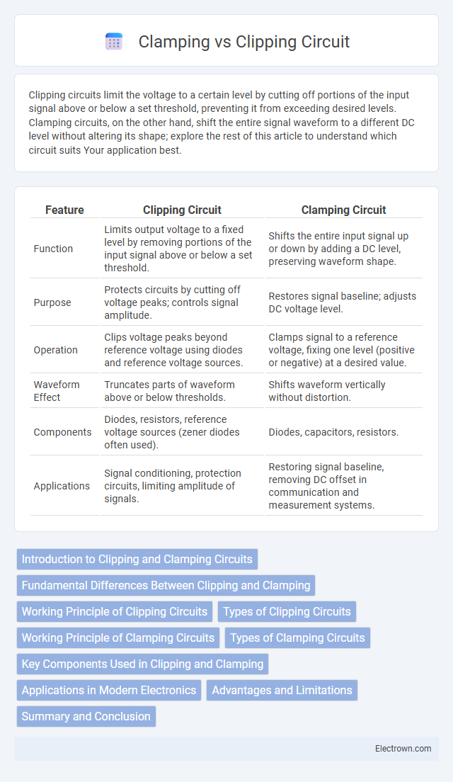
| Feature | Clipping Circuit | Clamping Circuit |
|---|---|---|
| Function | Limits output voltage to a fixed level by removing portions of the input signal above or below a set threshold. | Shifts the entire input signal up or down by adding a DC level, preserving waveform shape. |
| Purpose | Protects circuits by cutting off voltage peaks; controls signal amplitude. | Restores signal baseline; adjusts DC voltage level. |
| Operation | Clips voltage peaks beyond reference voltage using diodes and reference voltage sources. | Clamps signal to a reference voltage, fixing one level (positive or negative) at a desired value. |
| Waveform Effect | Truncates parts of waveform above or below thresholds. | Shifts waveform vertically without distortion. |
| Components | Diodes, resistors, reference voltage sources (zener diodes often used). | Diodes, capacitors, resistors. |
| Applications | Signal conditioning, protection circuits, limiting amplitude of signals. | Restoring signal baseline, removing DC offset in communication and measurement systems. |
Introduction to Clipping and Clamping Circuits
Clipping and clamping circuits are essential in electronics for shaping voltage waveforms; clipping circuits limit the output voltage to a specified level by removing portions of the input signal, while clamping circuits shift the entire waveform to a different DC level without altering its shape. Clipping circuits use diodes to cut off voltages above or below a set threshold, protecting components from voltage spikes. Clamping circuits typically involve capacitors and diodes to add a DC offset, making them crucial for signal processing and waveform shaping applications.
Fundamental Differences Between Clipping and Clamping
Clipping circuits limit the voltage by cutting off portions of the input signal that exceed a specific threshold, effectively shaping the waveform by removing peaks. Clamping circuits, on the other hand, shift the entire signal voltage level to a different DC reference without altering the signal shape, maintaining all original peaks but repositioned on the voltage axis. Understanding these fundamental differences helps you choose the appropriate circuit for controlling voltage levels in signal processing applications.
Working Principle of Clipping Circuits
Clipping circuits control voltage levels by limiting the output signal to a specific reference voltage, effectively "clipping" parts of the waveform that exceed this threshold. Using diodes and resistors, the circuit prevents voltage from rising above or falling below set limits, protecting components from voltage spikes. Your device benefits from this precise voltage regulation, maintaining signal integrity and preventing distortion in sensitive electronics.
Types of Clipping Circuits
Clipping circuits are designed to limit voltage signals by cutting off portions that exceed a certain threshold, and they come in two main types: series and shunt (parallel) clippers, each tailored to control either the positive or negative peaks of a waveform. Series clippers use a diode in series with the load to block voltage beyond a set limit, while shunt clippers employ a diode in parallel to divert excess voltage away from the load. Understanding these clipping circuit types helps you protect sensitive electronic components from voltage spikes by selecting the appropriate method for waveform shaping.
Working Principle of Clamping Circuits
Clamping circuits work by shifting the entire input signal waveform to a different DC level without altering its shape, using a combination of capacitors, diodes, and a reference voltage. The capacitor stores charge during one half-cycle, which then adds to or subtracts from the input voltage during the opposite half-cycle, effectively 'clamping' the output to a specified voltage level. This operation ensures the output signal is shifted up or down, maintaining the signal integrity while preventing it from going below or above a certain threshold.
Types of Clamping Circuits
Clamping circuits are primarily classified into positive clamping and negative clamping types, each designed to shift waveform levels without distortion. Positive clamping circuits restore DC components by shifting the signal to a new baseline above zero volts, while negative clamping circuits shift the waveform below zero volts to maintain the negative peak at zero. Variations such as bi-directional clampers and peak clamping circuits adapt these principles for AC signals and specific peak voltage maintaining applications.
Key Components Used in Clipping and Clamping
Clipping circuits primarily use diodes, resistors, and reference voltage sources to limit voltage levels by cutting off signals beyond a set threshold, protecting sensitive electronic components. Clamping circuits utilize diodes, capacitors, and resistors to shift the entire signal waveform vertically, maintaining its shape while altering the DC level. Both circuits rely on the diode's directional conductivity and the capacitor's charge storage to achieve voltage regulation and waveform modification.
Applications in Modern Electronics
Clipping circuits protect sensitive components in audio and communication systems by limiting voltage levels, preventing signal distortion and damage. Clamping circuits stabilize signal waveforms in digital electronics and display devices by shifting voltage levels to a desired reference point, ensuring consistent signal interpretation. Both circuits are essential for enhancing reliability and performance in power supplies, signal processing, and semiconductor devices.
Advantages and Limitations
Clipping circuits protect electronic components by limiting voltage to a predefined level, preventing signal distortion in audio and communication systems. They offer simplicity, fast response, and are effective for signal waveform shaping, but may introduce signal loss and distortion if voltage thresholds are not accurately set. Clamping circuits stabilize voltage levels by shifting signal reference points, improving signal integrity without altering waveform shape, yet they require precise biasing and may not protect against voltage spikes effectively.
Summary and Conclusion
Clipping circuits limit the voltage signal by cutting off portions that exceed a designated threshold, preventing distortion or damage in electronic systems. In contrast, clamping circuits shift the voltage level of a signal without altering its shape, maintaining the waveform within a specified voltage range. Both techniques are essential for signal conditioning in analog electronics, ensuring signal integrity and protecting circuit components.
clipping vs clamping circuit Infographic