Common mode signals occur when identical voltages appear on both inputs relative to ground, often causing unwanted noise in electronic circuits, while differential mode signals involve voltage differences between two inputs and are essential for accurate signal transmission. Understanding these concepts is crucial for improving Your circuit design and noise reduction strategies; explore the rest of the article to grasp their applications and differences fully.
Table of Comparison
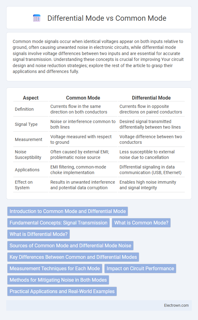
| Aspect | Common Mode | Differential Mode |
|---|---|---|
| Definition | Currents flow in the same direction on both conductors | Currents flow in opposite directions on paired conductors |
| Signal Type | Noise or interference common to both lines | Desired signal transmitted differentially between two lines |
| Measurement | Voltage measured with respect to ground | Voltage difference between two conductors |
| Noise Susceptibility | Often caused by external EMI; problematic noise source | Less susceptible to external noise due to cancellation |
| Applications | EMI filtering, common-mode choke implementation | Differential signaling in data communication (USB, Ethernet) |
| Effect on System | Results in unwanted interference and potential data corruption | Enables high noise immunity and signal integrity |
Introduction to Common Mode and Differential Mode
Common mode and differential mode are two primary types of electrical signals used in signal transmission and noise analysis. Common mode refers to signals that appear simultaneously and in phase on two or more conductors relative to a common ground, often causing interference and electromagnetic compatibility challenges. Differential mode involves signals that are equal in magnitude but opposite in phase between two conductors, enabling effective noise rejection and improved signal integrity in communication systems.
Fundamental Concepts: Signal Transmission
Differential mode involves signal transmission where two complementary signals are sent across paired conductors, enhancing noise immunity by allowing interference to be canceled out at the receiver. Common mode occurs when the same noise voltage appears simultaneously on both conductors relative to a common ground, often causing interference in sensitive equipment. Understanding these fundamental concepts helps you design robust communication systems with improved signal integrity and reduced susceptibility to electromagnetic interference.
What is Common Mode?
Common mode refers to electrical signals or noise that appear simultaneously and in phase on two or more conductors relative to a common reference point, usually ground. It often results from external electromagnetic interference or imbalances in the circuit and can cause signal distortion or equipment malfunction if not properly managed. Common mode signals are distinct from differential mode signals, which are transmitted as voltage differences between conductors.
What is Differential Mode?
Differential mode refers to the operation where signals are transmitted as the voltage difference between two conductors, enhancing noise immunity by rejecting common-mode interference. This technique is widely used in electronic communication systems, such as USB and Ethernet, to ensure data integrity over long distances. Differential mode signals provide higher signal-to-noise ratios compared to common mode, making them essential for high-speed data transmission and precision measurements.
Sources of Common Mode and Differential Mode Noise
Common mode noise typically originates from external electromagnetic interference, ground loop currents, and power supply fluctuations affecting all lines equally relative to ground. Differential mode noise arises from inherent circuit imbalances, switching transients, and crosstalk between signal lines, causing voltage differences between conductors. Understanding these noise sources is essential for effective noise mitigation in electronic systems and communication channels.
Key Differences Between Common and Differential Modes
Common mode signals appear identically on both conductors with respect to ground, while differential mode signals are equal in magnitude but opposite in polarity between the two conductors. Common mode interference often originates from external electromagnetic sources and affects both lines simultaneously, whereas differential mode noise is caused by imbalances within the signal path itself. Understanding these distinctions helps optimize noise reduction strategies in your electronic circuits for improved signal integrity and performance.
Measurement Techniques for Each Mode
Common mode measurement techniques typically involve using a differential probe connected to both inputs of an oscilloscope to capture voltage signals relative to a shared ground reference, ensuring noise common to both lines is detected. Differential mode measurement requires probes connected across the two signal lines, measuring the voltage difference directly between them, which helps to identify noise or signal integrity issues specific to the differential pair. Specialized equipment like isolation amplifiers or voltage isolators may be used to improve accuracy and safety when measuring high common mode voltages.
Impact on Circuit Performance
Common mode noise can significantly degrade circuit performance by introducing interference that affects all signal lines simultaneously, leading to signal distortion and reduced noise immunity. Differential mode signals improve circuit reliability by allowing the system to reject common noise, enhancing signal integrity and overall performance. Understanding the balance between common mode and differential mode is crucial for optimizing Your circuit's noise rejection and ensuring accurate data transmission.
Methods for Mitigating Noise in Both Modes
Effective noise mitigation in common mode involves implementing common-mode chokes and balanced cabling to suppress interference evenly across signal lines. For differential mode noise, techniques such as differential amplifiers, twisted pair wiring, and proper grounding minimize voltage differences causing signal degradation. Layered filtering methods and shielded cables are crucial in reducing both common and differential mode noise for enhanced signal integrity in electronic circuits.
Practical Applications and Real-World Examples
Common mode noise frequently appears in power supply lines and communication cables, often mitigated using common mode chokes to enhance signal integrity in data transmission systems. Differential mode signals are critical in Ethernet and USB interfaces, where differential signaling reduces electromagnetic interference and improves noise immunity for high-speed data communication. Practical applications of differential mode include audio equipment and sensor circuits, where precise signal measurement requires rejecting common mode noise.
common mode vs differential mode Infographic