An RC circuit uses resistors and capacitors to control voltage and store energy in the electric field, ideal for filtering and timing applications, while an RL circuit employs resistors and inductors to manage current and store energy in the magnetic field, often used in signal processing and inductive loads. Discover how understanding these differences can enhance Your electronic designs by reading the rest of the article.
Table of Comparison
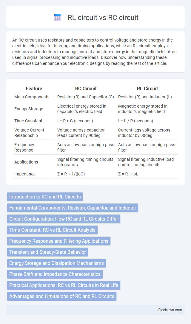
| Feature | RC Circuit | RL Circuit |
|---|---|---|
| Main Components | Resistor (R) and Capacitor (C) | Resistor (R) and Inductor (L) |
| Energy Storage | Electrical energy stored in capacitor's electric field | Magnetic energy stored in inductor's magnetic field |
| Time Constant | t = R x C (seconds) | t = L / R (seconds) |
| Voltage-Current Relationship | Voltage across capacitor leads current by 90deg | Current lags voltage across inductor by 90deg |
| Frequency Response | Acts as low-pass or high-pass filter | Acts as low-pass or high-pass filter |
| Applications | Signal filtering, timing circuits, integrators | Signal filtering, inductive load control, tuning circuits |
| Impedance | Z = R + 1/(joC) | Z = R + joL |
Introduction to RC and RL Circuits
RC circuits consist of resistors and capacitors, primarily used for filtering and timing applications due to their ability to store and release energy in the electric field. RL circuits combine resistors and inductors, focusing on managing current changes and electromagnetic energy storage with applications in signal processing and inductive load control. Understanding how your circuit behaves with either component combination optimizes performance for specific electrical functions.
Fundamental Components: Resistor, Capacitor, and Inductor
An RC circuit consists of a resistor and a capacitor, where the capacitor stores energy in an electric field and influences voltage changes over time, while the resistor controls the current flow and dissipates energy as heat. An RL circuit combines a resistor and an inductor, with the inductor storing energy in a magnetic field and opposing changes in current, and the resistor limiting the current and reducing energy loss. Your choice between RC and RL circuits depends on whether voltage or current response dominates your application, reflecting the fundamental roles of capacitors and inductors alongside resistors.
Circuit Configuration: How RC and RL Circuits Differ
RC circuits consist of a resistor and a capacitor connected in series or parallel, creating a frequency-dependent impedance primarily influenced by capacitive reactance. RL circuits feature a resistor and an inductor arranged similarly, where inductive reactance dictates the circuit's behavior across frequencies. The key difference lies in the energy storage element: capacitors store energy in an electric field, while inductors store energy in a magnetic field, leading to distinct transient responses and frequency characteristics.
Time Constant: RC vs RL Circuit Analysis
The time constant in an RC circuit is defined as t = R x C, representing the rate at which the capacitor charges or discharges through the resistor, significantly influencing voltage changes over time. In contrast, the RL circuit time constant is t = L / R, determining the rate of current growth or decay in the inductor-resistor loop, affecting magnetic energy storage and dissipation. Understanding the distinct time constants is critical for designing circuits with precise transient response characteristics and frequency behavior.
Frequency Response and Filtering Applications
RC circuits exhibit a frequency response characterized by a low-pass or high-pass filter behavior, where capacitive reactance decreases with frequency, allowing them to effectively filter out unwanted signals in audio and signal processing applications. RL circuits, dominated by the coil's inductive reactance increasing with frequency, are commonly used in high-frequency filtering and tuning applications, offering sharper cutoff characteristics compared to RC filters. Understanding your system's frequency response requirements enables you to select RC circuits for smoother filtering and RL circuits for more selective frequency attenuation or amplification.
Transient and Steady-State Behavior
In RC circuits, the transient behavior involves the capacitor charging or discharging exponentially with a time constant t = RC, leading to a smooth voltage transition before reaching steady-state. RL circuits exhibit transient currents that rise or decay exponentially with a time constant t = L/R, reflecting the inductor's opposition to changes in current. Understanding these distinctions helps you analyze circuit response times and steady-state voltage or current levels effectively.
Energy Storage and Dissipation Mechanisms
An RC circuit stores energy primarily in the electric field within the capacitor, dissipating energy through the resistor as heat via resistive losses. In contrast, an RL circuit stores energy in the magnetic field generated by the inductor, with energy also dissipated through the resistor as heat. Understanding these mechanisms can help you optimize circuit design for energy efficiency and response time in applications like filtering or signal processing.
Phase Shift and Impedance Characteristics
An RC circuit exhibits a phase shift where the voltage lags the current due to the capacitor's reactive impedance, causing the overall impedance to decrease with increasing frequency. In contrast, an RL circuit has a phase shift where the voltage leads the current because of the inductor's inductive reactance, resulting in impedance that increases with frequency. Understanding these phase and impedance behaviors helps You optimize circuit performance for filtering, timing, and signal processing applications.
Practical Applications: RC vs RL Circuits in Real Life
RC circuits are widely used in timing devices, filters, and signal processing due to their ability to store and release energy in capacitors, enabling precise control over voltage and phase shifts. RL circuits are commonly found in applications involving inductive loads, such as transformers, motors, and inductors in power supplies, where managing current changes and magnetic fields is crucial. Both circuits are essential in electronics, with RC circuits excelling in signal conditioning and RL circuits in managing electromagnetic energy.
Advantages and Limitations of RC and RL Circuits
RC circuits offer advantages such as efficient filtering of low-frequency signals and stable phase shifts, making them ideal for timing and waveform shaping applications; however, their performance is limited by capacitor size and leakage currents. RL circuits excel in handling high-frequency signals and provide significant inductive reactance, beneficial for energy storage and filtering, but their bulky inductors and susceptibility to electromagnetic interference pose design challenges. Understanding these limitations and advantages helps you select the appropriate circuit for applications involving signal processing, power regulation, or frequency modulation.
RC circuit vs RL circuit Infographic