A source follower offers a high input impedance and a voltage gain slightly less than one, making it ideal for impedance matching, while a drain follower typically features lower input impedance and less common usage due to its higher output impedance. Understanding these differences can significantly improve Your circuit design; continue reading to explore their applications and performance in detail.
Table of Comparison
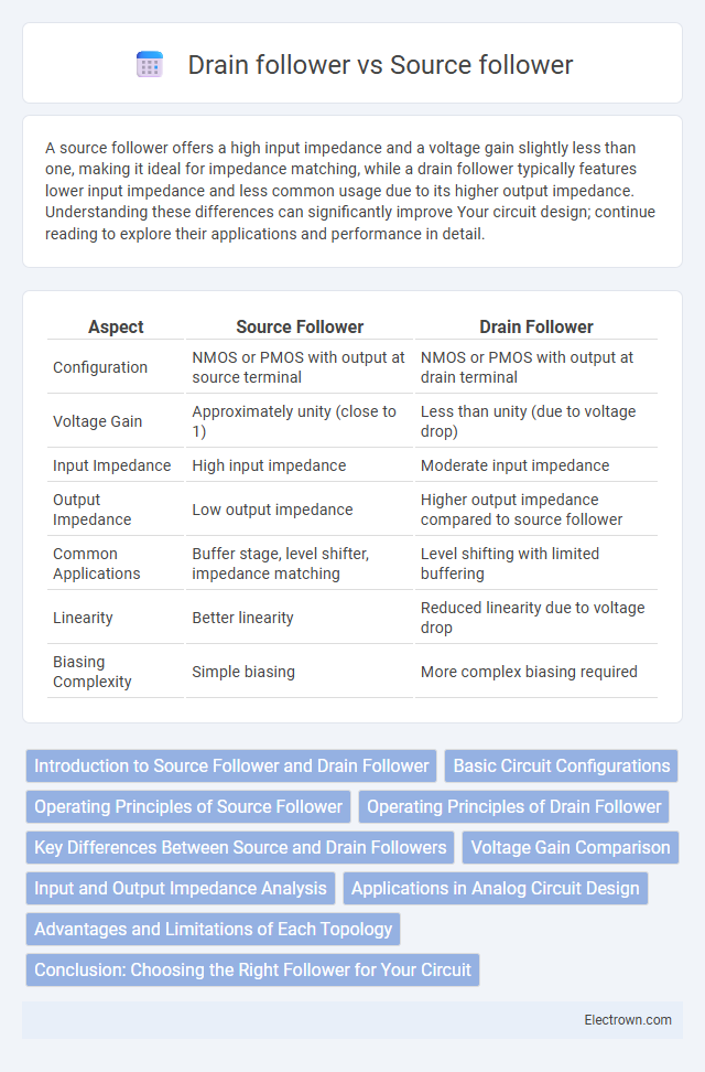
| Aspect | Source Follower | Drain Follower |
|---|---|---|
| Configuration | NMOS or PMOS with output at source terminal | NMOS or PMOS with output at drain terminal |
| Voltage Gain | Approximately unity (close to 1) | Less than unity (due to voltage drop) |
| Input Impedance | High input impedance | Moderate input impedance |
| Output Impedance | Low output impedance | Higher output impedance compared to source follower |
| Common Applications | Buffer stage, level shifter, impedance matching | Level shifting with limited buffering |
| Linearity | Better linearity | Reduced linearity due to voltage drop |
| Biasing Complexity | Simple biasing | More complex biasing required |
Introduction to Source Follower and Drain Follower
A source follower is a transistor configuration where the output voltage follows the input voltage with a gain slightly less than unity, commonly used for impedance matching due to its high input impedance and low output impedance. The drain follower, also known as the common drain amplifier, provides similar voltage buffering behavior, but the output is taken from the drain terminal, often utilized in MOSFET circuits for stable voltage gain near unity. Both topologies are essential in analog circuit design for buffering and signal isolation, differing mainly in their terminal connections and specific transistor types used.
Basic Circuit Configurations
The source follower, also known as the common-drain configuration, features the output taken from the source terminal of a MOSFET, providing a low output impedance and voltage gain close to unity. In contrast, the drain follower configuration, or common-source with resistive load, takes the output from the drain terminal, offering higher voltage gain but typically higher output impedance and phase inversion. Both configurations are fundamental in analog circuit design, with the source follower preferred for impedance matching and buffering, while the drain follower is used for amplification stages requiring gain.
Operating Principles of Source Follower
The source follower operates by using the MOSFET's source terminal as the output, which follows the input voltage applied to the gate, providing high input impedance and low output impedance. This circuit configuration maintains a voltage gain close to unity while offering current gain, making it ideal for impedance matching in analog circuits. The drain follower, in contrast, uses the drain terminal as the output but is less common due to its lower input impedance and less favorable voltage buffering characteristics.
Operating Principles of Drain Follower
The drain follower operates by maintaining the output voltage at the drain terminal, leveraging the transistor's gate-to-source voltage to stabilize the output and ensure low output impedance. It uses a MOSFET with the source connected to the input signal and the drain serving as the output node, providing voltage buffering with minimal signal distortion. This configuration offers improved voltage gain stability compared to the source follower, making it suitable for applications requiring precise voltage levels.
Key Differences Between Source and Drain Followers
Source followers feature their output at the source terminal, providing low output impedance and a voltage gain slightly less than unity, making them ideal for impedance matching and buffering applications. Drain followers, less common in analog design, have output at the drain terminal and typically offer higher output impedance, which can be beneficial in specific high-frequency or switching scenarios. Your choice between source and drain followers depends on the required output impedance, voltage gain, and application-specific performance needs.
Voltage Gain Comparison
Source followers typically provide a voltage gain slightly less than unity, around 0.9 to 0.99, due to the MOSFET's intrinsic gain and source degeneration. Drain followers, unlike source followers, generally have very low voltage gain close to unity but are less commonly used because of their poor linearity and higher output impedance. Your choice depends on the specific circuit requirements, as source followers offer better voltage buffering with minimal gain loss.
Input and Output Impedance Analysis
Source followers typically exhibit high input impedance and low output impedance, making them ideal for buffering and impedance matching in analog circuits. Drain followers, however, have comparatively lower input impedance and higher output impedance, limiting their effectiveness in driving low-impedance loads. Understanding these impedance characteristics helps you choose the appropriate follower configuration for efficient signal transfer and minimal loading effects.
Applications in Analog Circuit Design
Source followers are widely used in analog circuit design for impedance buffering and voltage level shifting, offering high input impedance and low output impedance, which makes them ideal for driving capacitive loads and interfacing between high-impedance sensors and subsequent stages. Drain followers, though less common, are utilized in specific analog circuits requiring a low output impedance with a voltage gain close to unity, often found in certain operational amplifier output stages and current mirror circuits. The choice between source and drain followers depends on parameters like voltage gain, linearity, and power consumption relevant to the targeted analog application.
Advantages and Limitations of Each Topology
Source followers offer high input impedance and excellent voltage buffering with low output impedance, making them ideal for impedance matching in analog circuits; however, they typically suffer from a limited voltage swing due to threshold voltage drop. Drain followers provide a wider voltage swing and can operate at higher frequencies, but their lower input impedance and higher output impedance reduce their effectiveness in buffering applications. Each topology's choice depends on the specific requirements for input/output impedance, voltage swing, and frequency response in the design.
Conclusion: Choosing the Right Follower for Your Circuit
Source followers offer high input impedance and low output impedance, making them ideal for voltage buffering and impedance matching in most analog circuits. Drain followers typically provide a constant current output but suffer from lower input impedance and higher distortion, limiting their use to specialized applications. Evaluate your circuit's impedance requirements and signal integrity needs to choose the most suitable follower for your design.
source follower vs drain follower Infographic