The hybrid-pi model provides a more accurate representation of a transistor's small-signal behavior by incorporating both input and output resistances and transconductance, while the T-model focuses primarily on the transistor's current gain and input resistance for simplification in certain circuit analyses. Understanding the distinctions and applications of these models can enhance Your circuit design and analysis skills; continue reading to explore their differences and practical uses.
Table of Comparison
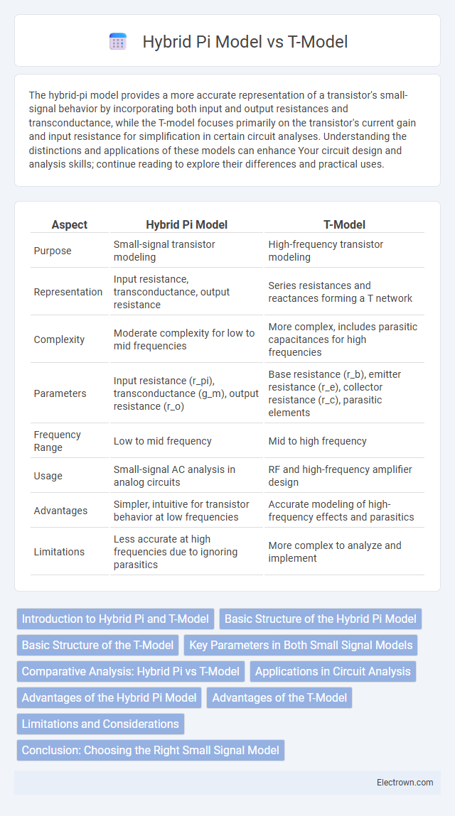
| Aspect | Hybrid Pi Model | T-Model |
|---|---|---|
| Purpose | Small-signal transistor modeling | High-frequency transistor modeling |
| Representation | Input resistance, transconductance, output resistance | Series resistances and reactances forming a T network |
| Complexity | Moderate complexity for low to mid frequencies | More complex, includes parasitic capacitances for high frequencies |
| Parameters | Input resistance (r_pi), transconductance (g_m), output resistance (r_o) | Base resistance (r_b), emitter resistance (r_e), collector resistance (r_c), parasitic elements |
| Frequency Range | Low to mid frequency | Mid to high frequency |
| Usage | Small-signal AC analysis in analog circuits | RF and high-frequency amplifier design |
| Advantages | Simpler, intuitive for transistor behavior at low frequencies | Accurate modeling of high-frequency effects and parasitics |
| Limitations | Less accurate at high frequencies due to ignoring parasitics | More complex to analyze and implement |
Introduction to Hybrid Pi and T-Model
The Hybrid Pi model represents a transistor using a voltage-controlled current source, emphasizing small-signal parameters like transconductance (gm) and input resistance (rp) to analyze high-frequency behavior. The T-model, on the other hand, simplifies transistor modeling into a resistance network focusing on emitter resistance (re) and base spreading resistance, facilitating easier understanding of low-frequency characteristics. Both models are essential in electronic circuit design for optimizing transistor performance in different frequency ranges.
Basic Structure of the Hybrid Pi Model
The basic structure of the Hybrid Pi Model consists of a controlled current source representing the transistor's transconductance (gm) and resistive elements such as rp that model the input resistance between the base and emitter. This small-signal equivalent circuit captures both the intrinsic base-emitter junction behavior and the transistor gain, facilitating accurate frequency response analysis. The model also includes parameters like r0 (output resistance) to represent the Early effect, making it suitable for detailed amplifier design and simulation.
Basic Structure of the T-Model
The basic structure of the T-Model consists of a series impedance and a shunt admittance forming a "T" shape, representing the transistor's internal resistances and capacitances. This model simplifies the transistor by focusing on input resistance, output resistance, and current gain, making it ideal for analyzing low-frequency transistor behavior. Unlike the Hybrid Pi model, which uses a more complex representation with transconductance and rp parameters, the T-Model offers an intuitive approach for understanding the transistor's internal feedback mechanisms.
Key Parameters in Both Small Signal Models
The Hybrid p model and T-model are essential small signal models in transistor analysis, where key parameters differ based on configuration; the Hybrid p model emphasizes transconductance (gm) and input resistance (rp), while the T-model highlights the base spreading resistance (rb) and transconductance (gm). Both models incorporate output resistance (ro) to account for the Early effect, but the relationship between input and output parameters varies, impacting the analysis of gain and input impedance. Choosing the right model depends on Your circuit's focus, with the Hybrid p model often preferred for voltage gain calculations and the T-model better suited for current and impedance characterization.
Comparative Analysis: Hybrid Pi vs T-Model
The Hybrid Pi model offers a more detailed representation of transistor behavior, including base-emitter diffusion capacitance and transconductance parameters, making it ideal for high-frequency analysis. The T-model simplifies the transistor into a network of resistances and controlled current sources, beneficial for low-frequency or small-signal analysis due to its straightforward approach. Understanding these differences helps you choose the appropriate model for accurate circuit design and simulation based on frequency and complexity requirements.
Applications in Circuit Analysis
The Hybrid pi model is extensively used in transistor small-signal analysis due to its accurate representation of input resistance, output resistance, and current gain, making it ideal for evaluating voltage gain and input/output impedance in amplifiers. In contrast, the T-model simplifies the transistor's internal resistances and is often applied in low-frequency analysis and current-driven circuits, offering easier calculations for emitter follower configurations. Your choice between these models depends on the specific circuit parameters and frequency domain requirements to enhance analysis precision.
Advantages of the Hybrid Pi Model
The Hybrid Pi Model offers superior accuracy in representing the small-signal behavior of bipolar junction transistors (BJTs) by explicitly modeling both input resistance and current gain mechanisms, which enhances circuit analysis precision. Its inclusion of parameters such as transconductance (gm) and output resistance (ro) allows for more detailed simulation of frequency response and gain, outperforming the simpler T-model in predicting real-world transistor performance. This improved parameterization makes the Hybrid Pi Model particularly advantageous for high-frequency amplifier design and transistor-level circuit optimization.
Advantages of the T-Model
The T-model offers simplified analysis of bipolar junction transistors by representing them with fewer components, making it easier to calculate input and output impedances. This model provides more accurate representation at both low and high frequencies compared to the hybrid pi model, enhancing circuit design precision. Its straightforward structure improves understanding of transistor behavior in amplifier configurations without sacrificing analytical accuracy.
Limitations and Considerations
The Hybrid pi model provides more accurate high-frequency behavior representation by including transistor parasitics but requires complex parameter extraction, making it less practical for quick circuit analysis. The T-model simplifies calculations for low-frequency small-signal analysis but neglects frequency-dependent effects, limiting its accuracy in high-frequency applications. Engineers must consider the trade-off between model complexity and frequency response accuracy when selecting between these transistor models.
Conclusion: Choosing the Right Small Signal Model
The choice between the Hybrid pi model and the T-model depends on the specific small-signal analysis requirements of bipolar junction transistors (BJTs). The Hybrid pi model excels in accurately representing input impedance and voltage gain in common-emitter configurations, making it ideal for high-frequency applications. The T-model offers simpler current-based analysis and is preferred for low-frequency or circuit scenarios focusing on current relations, highlighting the importance of matching model selection to the frequency range and analysis focus.
Hybrid pi model vs T-model Infographic