Matching networks optimize the transfer of power between circuits by aligning their impedances, often using reactive components like inductors and capacitors to minimize reflections. Understanding the differences between matching networks and impedance transformers can enhance Your circuit design efficiency; explore the full article to discover their unique applications and benefits.
Table of Comparison
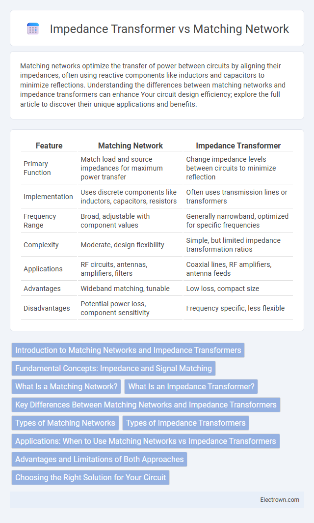
| Feature | Matching Network | Impedance Transformer |
|---|---|---|
| Primary Function | Match load and source impedances for maximum power transfer | Change impedance levels between circuits to minimize reflection |
| Implementation | Uses discrete components like inductors, capacitors, resistors | Often uses transmission lines or transformers |
| Frequency Range | Broad, adjustable with component values | Generally narrowband, optimized for specific frequencies |
| Complexity | Moderate, design flexibility | Simple, but limited impedance transformation ratios |
| Applications | RF circuits, antennas, amplifiers, filters | Coaxial lines, RF amplifiers, antenna feeds |
| Advantages | Wideband matching, tunable | Low loss, compact size |
| Disadvantages | Potential power loss, component sensitivity | Frequency specific, less flexible |
Introduction to Matching Networks and Impedance Transformers
Matching networks optimize signal transfer by minimizing reflection between different impedance levels, ensuring maximum power delivery in RF systems. Impedance transformers specifically convert one impedance value to another, often using components like transmission lines or lumped elements to achieve the desired impedance transformation. You benefit from understanding both concepts to design efficient communication circuits that reduce loss and improve overall performance.
Fundamental Concepts: Impedance and Signal Matching
Matching networks optimize signal transfer by aligning the impedance of a source and load to minimize reflections and maximize power delivery. Impedance transformers function by converting one impedance level to another, often using reactive components like inductors and capacitors to achieve this transformation over a specific frequency range. Both concepts rely on fundamental transmission line principles to ensure efficient signal matching in RF and microwave systems.
What Is a Matching Network?
A matching network is an electrical circuit designed to optimize power transfer between components by equalizing impedance values, minimizing reflection and signal loss. It typically consists of inductors, capacitors, or transmission lines arranged to adjust the source and load impedances for maximum efficiency. Understanding your matching network ensures improved signal integrity and enhanced performance in RF and microwave systems.
What Is an Impedance Transformer?
An impedance transformer is a device designed to efficiently transfer electrical energy between circuits with different impedances by altering the load impedance to match the source impedance, minimizing signal reflection and power loss. Unlike a matching network that can consist of various components configured to achieve impedance matching over a broad frequency range, an impedance transformer typically uses specific transmission line sections or transformers to achieve precise impedance scaling at designated frequencies. This targeted impedance adjustment enhances system performance in RF circuits, antennas, and communication systems by maximizing power transfer and signal integrity.
Key Differences Between Matching Networks and Impedance Transformers
Matching networks optimize signal transfer by adjusting impedance across a range of frequencies, using components like inductors and capacitors configured in networks such as L, Pi, or T. Impedance transformers typically employ transmission line sections or transformers to convert one specific impedance value to another, focusing on narrowband applications. Your choice depends on whether broadband matching (matching network) or precise narrowband conversion (impedance transformer) best suits your system requirements.
Types of Matching Networks
Matching networks include L-networks, Pi-networks, and T-networks, each designed to optimize impedance matching for different frequency ranges and power levels. Impedance transformers often utilize quarter-wave transmission line sections or baluns to achieve a specific impedance transformation ratio. Selection between these types depends on application requirements such as bandwidth, power handling, and circuit complexity.
Types of Impedance Transformers
Impedance transformers include various types such as quarter-wave transformers, transformer coils, and tapered transmission lines, each designed to efficiently match impedances between network components. Matching networks, on the other hand, often combine reactive elements like inductors and capacitors into L, T, or Pi configurations to optimize signal transfer and minimize reflection. Your choice depends on frequency range, bandwidth requirements, and physical constraints of the system you are designing.
Applications: When to Use Matching Networks vs Impedance Transformers
Matching networks are ideal for complex impedance matching in RF circuits where frequency response and bandwidth optimization are critical, such as in antenna systems and amplifiers. Impedance transformers excel in scenarios requiring simple, fixed impedance conversion at a single frequency or narrow band, commonly used in transmission lines and power transfer applications. Selecting between a matching network and an impedance transformer depends largely on application frequency range, load variability, and design complexity.
Advantages and Limitations of Both Approaches
Matching networks provide broadband impedance matching with the ability to optimize power transfer and minimize signal reflection across a wide frequency range, but they often require complex circuit designs and component tuning. Impedance transformers offer simpler, more efficient solutions for specific frequency ranges by transforming impedances through transmission line segments or transformers, yet their narrow bandwidth and fixed matching characteristics limit versatility. Both techniques play crucial roles in RF and microwave systems, where the choice depends on application requirements, bandwidth needs, and design complexity.
Choosing the Right Solution for Your Circuit
Matching networks optimize signal transfer by ensuring impedance compatibility between circuit components, minimizing reflection and power loss across specific frequency ranges. Impedance transformers adjust impedance levels more broadly, often using transformers or transmission line segments, offering higher power handling and broadband performance ideal for RF amplifiers and antennas. Your choice depends on the frequency range, power requirements, and circuit complexity, with matching networks suited for narrowband precision and impedance transformers favored for broadband or high-power applications.
matching network vs impedance transformer Infographic