Signal ground serves as a reference point for low-level, sensitive signals to minimize noise, while analog ground is designed to handle return currents from analog circuitry, often isolated to prevent interference. Understanding the distinction between signal ground and analog ground is crucial for optimizing your circuit's performance--read on to explore their roles in depth.
Table of Comparison
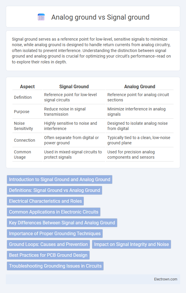
| Aspect | Signal Ground | Analog Ground |
|---|---|---|
| Definition | Reference point for low-level signal circuits | Reference point for analog circuit sections |
| Purpose | Reduce noise in signal transmission | Minimize interference in analog signals |
| Noise Sensitivity | Highly sensitive to noise and interference | Designed to isolate analog noise from digital |
| Connection | Often separate from digital or power ground | Typically tied to a clean, low-noise ground plane |
| Common Usage | Used in mixed-signal circuits to protect signals | Used for precision analog components and sensors |
Introduction to Signal Ground and Analog Ground
Signal ground serves as the reference point in circuits for processing and transmitting data signals, minimizing electrical noise interference. Analog ground specifically relates to the reference return path in analog circuitry, ensuring precise voltage levels and stable signal integrity. Understanding the distinction between signal ground and analog ground helps you design systems with improved noise performance and accurate analog measurements.
Definitions: Signal Ground vs Analog Ground
Signal ground refers to a common reference point for digital signals, minimizing noise by keeping digital return paths separate from other circuits. Analog ground serves as the reference point for analog signals, ensuring accurate voltage levels and reducing interference in sensitive analog circuitry. Your circuit design benefits from clearly distinguishing between signal ground and analog ground to improve overall signal integrity and reduce cross-talk.
Electrical Characteristics and Roles
Signal ground serves as a stable reference point for low-level analog and digital signals, minimizing interference and noise in sensitive circuits through high impedance characteristics and low current return paths. Analog ground is designed to handle return currents from analog components, ensuring a noise-free environment by providing a dedicated low-impedance path that isolates sensitive analog signals from digital switching noise. Proper separation and careful design of signal ground and analog ground planes reduce ground loops and electromagnetic interference, enhancing overall circuit performance and signal integrity.
Common Applications in Electronic Circuits
Signal ground and analog ground serve distinct roles in electronic circuits to minimize noise interference and ensure signal integrity. Common applications of signal ground include digital communication systems and microcontroller circuits where it acts as a reference point for digital signals. Analog ground is primarily used in sensitive analog circuits such as audio equipment, sensors, and measurement devices to provide a stable reference minimizing ground loop noise and interference.
Key Differences Between Signal and Analog Ground
Signal ground serves as a reference point for digital circuits to ensure accurate data transmission and reduce noise, while analog ground is dedicated to sensitive analog components to maintain signal integrity and minimize interference. The key differences lie in their purposes and noise tolerance: analog ground requires a cleaner, low-noise environment, whereas signal ground can tolerate higher noise levels typical in digital switching. Proper separation and careful layout of signal and analog grounds in your circuit design prevent ground loops and improve overall system performance.
Importance of Proper Grounding Techniques
Proper grounding techniques ensure signal ground remains free from noise and interference, crucial for accurate analog signal processing. Separating analog ground from digital ground prevents ground loops, reducing distortion and maintaining signal integrity. Effective grounding minimizes electromagnetic interference (EMI), enhancing overall system performance and reliability.
Ground Loops: Causes and Prevention
Ground loops occur when multiple ground paths create unwanted current flow between Signal ground and Analog ground, causing interference and noise in sensitive circuits. Causes include improper grounding schemes, differences in ground potentials, and long ground return paths that pick up electromagnetic interference. Prevention methods involve using a single-point ground, ensuring proper star grounding techniques, and isolating analog and digital grounds to minimize current loops and maintain signal integrity.
Impact on Signal Integrity and Noise
Signal ground and analog ground play critical roles in maintaining signal integrity and minimizing noise in electronic systems. Separating signal ground from analog ground reduces interference by isolating high-frequency digital noise from sensitive analog circuits, thus preserving the accuracy of your measurements. Proper grounding techniques ensure a stable reference point, minimizing voltage fluctuations and improving overall noise immunity.
Best Practices for PCB Ground Design
Signal ground and analog ground should be carefully separated on PCB layouts to minimize noise coupling and maintain signal integrity. A well-designed ground plane with low impedance paths ensures proper return current flow and reduces electromagnetic interference (EMI) in sensitive analog circuits. Connecting these grounds at a single, low-impedance point, often near the power supply, follows best practices for effective PCB ground design.
Troubleshooting Grounding Issues in Circuits
Troubleshooting grounding issues in circuits requires a clear distinction between signal ground and analog ground to minimize noise interference and ground loops. Signal ground serves as a reference point for low-level signals, while analog ground handles sensitive analog circuitry, and improper separation can cause ground potential differences leading to erroneous readings or operational instability. Verifying the continuity and connection integrity between these grounds along with using star grounding techniques helps identify and resolve grounding problems effectively.
Signal ground vs analog ground Infographic