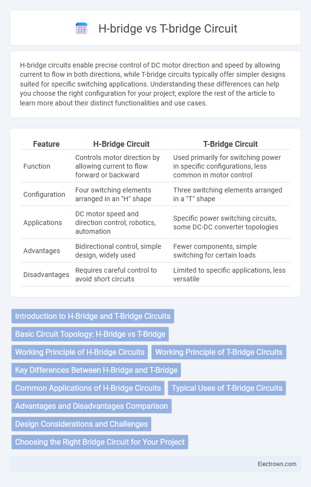
H-bridge circuits enable precise control of DC motor direction and speed by allowing current to flow in both directions, while T-bridge circuits typically offer simpler designs suited for specific switching applications. Understanding these differences can help you choose the right configuration for your project; explore the rest of the article to learn more about their distinct functionalities and use cases.
Table of Comparison
| Feature | H-Bridge Circuit | T-Bridge Circuit |
|---|---|---|
| Function | Controls motor direction by allowing current to flow forward or backward | Used primarily for switching power in specific configurations, less common in motor control |
| Configuration | Four switching elements arranged in an "H" shape | Three switching elements arranged in a "T" shape |
| Applications | DC motor speed and direction control, robotics, automation | Specific power switching circuits, some DC-DC converter topologies |
| Advantages | Bidirectional control, simple design, widely used | Fewer components, simple switching for certain loads |
| Disadvantages | Requires careful control to avoid short circuits | Limited to specific applications, less versatile |
Introduction to H-Bridge and T-Bridge Circuits
H-bridge circuits enable bidirectional control of DC motors by using four switching elements arranged in an "H" shape, allowing current to flow in either direction and thus controlling motor rotation. T-bridge circuits, less common than H-bridges, utilize a transistor-based configuration forming a "T" shape circuit layout to provide similar motor control functionality but with different switching arrangements and current paths. Both circuits are essential in motor driver applications, with H-bridges widely favored for their simplicity and versatility in controlling direction and speed.
Basic Circuit Topology: H-Bridge vs T-Bridge
The H-bridge circuit consists of four switches arranged in an "H" configuration to control the direction of current through a load, enabling bidirectional motor control. The T-bridge utilizes three switches forming a "T" shape, generally allowing simpler unidirectional control with reduced component count and complexity. The H-bridge topology is preferred for applications requiring reversible motor operation, while the T-bridge is suited for basic speed control where direction change is unnecessary.
Working Principle of H-Bridge Circuits
H-bridge circuits control the direction of current flow through a load, enabling bidirectional motor control by using four switching elements arranged in an "H" configuration. The working principle relies on selectively activating pairs of switches to reverse the polarity applied to the motor terminals, allowing it to rotate clockwise or counterclockwise. This switching mechanism provides precise control over motor speed and direction in applications such as robotics, electric vehicles, and industrial automation.
Working Principle of T-Bridge Circuits
T-bridge circuits operate by using a configuration of resistors and switches to control the direction and magnitude of current flow, enabling precise modulation of load voltage. This arrangement allows bidirectional current flow through the load, making it suitable for applications like motor control and AC signal generation. Compared to H-bridge circuits, T-bridge designs offer simpler layouts with fewer switching elements while maintaining effective control over output polarity and amplitude.
Key Differences Between H-Bridge and T-Bridge
H-bridge and T-bridge circuits differ primarily in their configuration and application; the H-bridge uses four switches arranged in an "H" shape to control the direction of current and motor rotation, while the T-bridge employs a different arrangement optimized for specific load control. H-bridges provide bidirectional control and are ideal for driving DC motors, offering full control over speed and direction, whereas T-bridges are often used in power electronics for switching and modulation tasks. Understanding these key differences helps you select the appropriate circuit design to ensure efficient motor control or power management in your electronic projects.
Common Applications of H-Bridge Circuits
H-bridge circuits are widely used in motor control applications, enabling bidirectional control of DC motors by reversing the current flow. They are essential in robotics, electric vehicles, and automated conveyor systems, where precise speed and direction management are critical. Your designs benefit from H-bridge circuits when implementing efficient and compact solutions for driving motors in embedded systems.
Typical Uses of T-Bridge Circuits
T-bridge circuits are commonly used in precision measurement applications, such as detecting small changes in resistance in strain gauges or sensors. Their ability to provide accurate differential output makes them ideal for temperature sensing, pressure measurement, and material testing. You can rely on T-bridge circuits to enhance accuracy in instrumentation and control systems where fine detection is critical.
Advantages and Disadvantages Comparison
H-bridge circuits offer precise control of motor direction and speed with simple design, making them ideal for DC motor applications, yet they suffer from complexity when scaling to higher voltages due to potential shoot-through issues. T-bridge circuits simplify switching by using fewer components and reduce power loss through low side switches, but they provide limited control flexibility and are less efficient for bidirectional motor control. Your choice depends on the application's requirement for control precision versus component simplicity and efficiency.
Design Considerations and Challenges
Designing an H-bridge circuit requires careful attention to switching timing and dead-time management to prevent shoot-through and ensure efficient motor control. T-bridge circuits present challenges in balancing voltage drops across components and maintaining symmetrical current flow for stable operation. Understanding these design considerations helps optimize your circuit's performance and reliability in power electronics applications.
Choosing the Right Bridge Circuit for Your Project
Choosing the right bridge circuit for your project depends on the required control and complexity; H-bridge circuits excel in driving DC motors with bidirectional control and variable speed, making them ideal for robotics and automation applications. T-bridge circuits are simpler and cost-effective for unidirectional current flow or switching applications but lack the versatility of H-bridges in reversing motor polarity. Evaluating power requirements, control precision, and circuit complexity ensures optimal performance and efficiency in your electronic design.
H-bridge vs T-bridge circuit Infographic