PNP and NPN transistors serve different roles in sensor circuits, with PNP transistors sourcing current to the load when activated, and NPN transistors sinking current from the load to ground; understanding their polarity and switching characteristics is crucial for designing efficient sensor interfaces. Explore the rest of the article to learn which transistor type best suits your sensor application and optimize Your circuit performance.
Table of Comparison
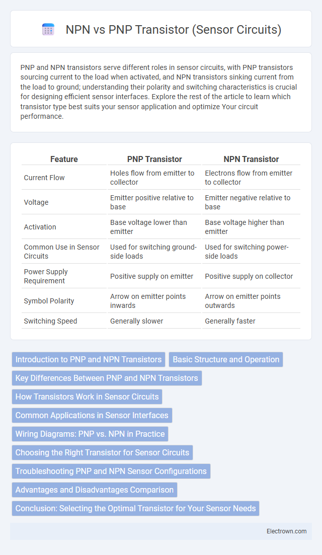
| Feature | PNP Transistor | NPN Transistor |
|---|---|---|
| Current Flow | Holes flow from emitter to collector | Electrons flow from emitter to collector |
| Voltage | Emitter positive relative to base | Emitter negative relative to base |
| Activation | Base voltage lower than emitter | Base voltage higher than emitter |
| Common Use in Sensor Circuits | Used for switching ground-side loads | Used for switching power-side loads |
| Power Supply Requirement | Positive supply on emitter | Positive supply on collector |
| Symbol Polarity | Arrow on emitter points inwards | Arrow on emitter points outwards |
| Switching Speed | Generally slower | Generally faster |
Introduction to PNP and NPN Transistors
PNP and NPN transistors are essential bipolar junction transistors used in sensor circuits for switching and amplification purposes. NPN transistors have electrons as majority carriers, allowing current flow when the base is supplied with positive voltage relative to the emitter, while PNP transistors use holes as majority carriers, conducting current when the base is at a lower potential than the emitter. These fundamental differences impact how each transistor type integrates into sensor circuit designs, influencing biasing and signal processing strategies.
Basic Structure and Operation
PNP and NPN transistors differ in their basic structure, where PNP transistors consist of a layer of N-type semiconductor between two P-type layers, while NPN transistors have a layer of P-type material between two N-type layers. In operation, NPN transistors allow current to flow when a positive voltage is applied to the base relative to the emitter, enabling electron flow from the emitter to the collector. PNP transistors operate oppositely, conducting current when the base is at a lower voltage than the emitter, facilitating hole flow from emitter to collector, making them suitable for different configurations in sensor circuits.
Key Differences Between PNP and NPN Transistors
PNP and NPN transistors differ primarily in the direction of current flow and the polarity of voltage required to operate them. In sensor circuits, NPN transistors conduct when a positive voltage is applied to the base relative to the emitter, allowing current to flow from the collector to the emitter, while PNP transistors conduct when the base is at a lower potential than the emitter, enabling current flow from emitter to collector. These polarity and current flow distinctions influence their integration into sensor circuits, with NPN transistors commonly used in low-side switching and PNP transistors preferred for high-side switching applications.
How Transistors Work in Sensor Circuits
PNP and NPN transistors function as switches or amplifiers in sensor circuits by controlling current flow based on the input signal. NPN transistors allow current to flow from the collector to the emitter when a positive voltage is applied to the base, commonly used for sinking current in sensor outputs. PNP transistors enable current flow from the emitter to the collector when the base is driven low, often utilized for sourcing current to sensors or loads in measurement systems.
Common Applications in Sensor Interfaces
PNP transistors in sensor circuits are commonly used for high-side switching applications where the load is connected to ground, allowing easy control of devices like temperature sensors or light sensors. NPN transistors serve as low-side switches, facilitating current flow toward ground and are frequently employed in interfacing digital output sensors or proximity detectors to microcontrollers. Both transistor types ensure efficient signal amplification and switching, optimizing sensor interface performance in embedded systems and industrial automation.
Wiring Diagrams: PNP vs. NPN in Practice
PNP and NPN transistors in sensor circuits differ primarily in wiring configurations; PNP transistors connect the load to the positive voltage supply and switch the ground path, while NPN transistors connect the load to ground and switch the positive voltage path. Understanding the wiring diagrams ensures correct polarity, with PNP sensors typically sourcing current to the controller input and NPN sensors sinking current from it. Your ability to interpret these wiring details directly impacts seamless integration and accurate sensor signals in electronic circuits.
Choosing the Right Transistor for Sensor Circuits
Choosing the right transistor for sensor circuits depends on the type of load and signal polarity; NPN transistors are preferred for switching to ground, offering faster response and better saturation for common negative logic sensors. PNP transistors are used when switching to the positive supply and are ideal in circuits requiring a sourcing current configuration. Your sensor circuit's voltage levels and current requirements directly influence whether an NPN or PNP transistor provides optimal performance and reliability.
Troubleshooting PNP and NPN Sensor Configurations
Troubleshooting PNP and NPN sensor configurations involves understanding their distinct current flow and output logic: PNP sensors source current, while NPN sensors sink it, meaning incorrect wiring or incompatible input modules often cause malfunction. Verify correct polarity and wiring by testing voltage levels at sensor outputs relative to common ground or power, ensuring proper sensor activation and signal transmission. Your troubleshooting process benefits from using a multimeter or oscilloscope to detect voltage presence and verify whether the sensor output correctly switches from high to low states under varying conditions.
Advantages and Disadvantages Comparison
PNP transistors in sensor circuits offer easier grounding and simpler wiring to positive voltage sources, making them advantageous for common positive supply systems, while their disadvantage includes slower switching speeds compared to NPN transistors. NPN transistors provide faster switching, better electron mobility, and greater efficiency in sinking current to ground, which is beneficial in high-speed sensor applications, but they can be less convenient in circuits with common positive supply due to more complex wiring. Choosing between PNP and NPN depends on specific application needs such as supply configuration, switching speed, and circuit simplicity.
Conclusion: Selecting the Optimal Transistor for Your Sensor Needs
Choosing between PNP and NPN transistors in sensor circuits depends on the application's voltage polarity and switching requirements. NPN transistors are preferred for low-side switching with a common ground, offering faster switching speeds and easier interfacing with microcontrollers. PNP transistors excel in high-side switching scenarios where the load is connected to ground, making them ideal for sensor circuits needing positive voltage control and simplified wiring configurations.
PNP vs NPN Transistor (Sensor Circuits) Infographic