Miller capacitors are used to model the feedback capacitance in amplifiers, influencing high-frequency response and stability, while bypass capacitors are employed to filter out noise and stabilize power supply voltages in circuits. Understanding the distinct roles and applications of these capacitors will help you optimize your electronic designs, so explore the rest of the article for detailed comparisons and practical tips.
Table of Comparison
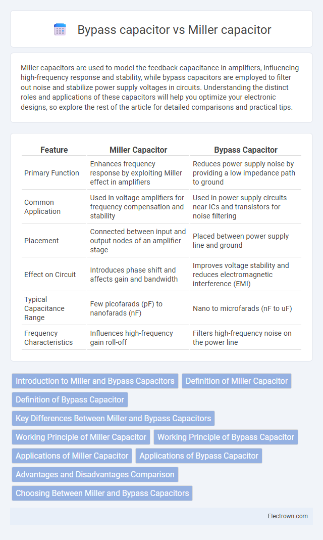
| Feature | Miller Capacitor | Bypass Capacitor |
|---|---|---|
| Primary Function | Enhances frequency response by exploiting Miller effect in amplifiers | Reduces power supply noise by providing a low impedance path to ground |
| Common Application | Used in voltage amplifiers for frequency compensation and stability | Used in power supply circuits near ICs and transistors for noise filtering |
| Placement | Connected between input and output nodes of an amplifier stage | Placed between power supply line and ground |
| Effect on Circuit | Introduces phase shift and affects gain and bandwidth | Improves voltage stability and reduces electromagnetic interference (EMI) |
| Typical Capacitance Range | Few picofarads (pF) to nanofarads (nF) | Nano to microfarads (nF to uF) |
| Frequency Characteristics | Influences high-frequency gain roll-off | Filters high-frequency noise on the power line |
Introduction to Miller and Bypass Capacitors
Miller capacitors are used in amplifier circuits to create feedback and influence frequency response by connecting between the input and output of an active device, effectively increasing the input capacitance. Bypass capacitors serve to stabilize voltage supply lines by filtering out noise and providing a low-impedance path to ground for high-frequency signals. Your circuit's performance and signal integrity depend significantly on selecting the appropriate capacitor type based on the specific function required in the design.
Definition of Miller Capacitor
A Miller capacitor is an intrinsic parasitic capacitor that appears between the input and output terminals of an amplifier due to feedback capacitance, effectively amplifying the input capacitance and impacting high-frequency response. Unlike bypass capacitors, which are external components used to filter noise and stabilize voltage supply lines, Miller capacitors influence circuit bandwidth and phase margin by introducing additional capacitance. Understanding the role of the Miller capacitor helps you optimize amplifier designs for better frequency performance and stability.
Definition of Bypass Capacitor
A bypass capacitor is an electronic component connected in parallel with a power supply line to ground, designed to reduce voltage fluctuations and filter out noise in a circuit. Unlike a Miller capacitor, which intentionally introduces feedback capacitance for frequency compensation, a bypass capacitor stabilizes power delivery by providing a low impedance path for transient currents. This ensures smoother operation of active components such as transistors and integrated circuits by minimizing supply voltage ripple.
Key Differences Between Miller and Bypass Capacitors
Miller capacitors are primarily used in amplifier circuits to stabilize gain and control frequency response by introducing feedback between input and output terminals, whereas bypass capacitors are designed to filter and shunt noise or AC signals to ground, enhancing power supply stability. The Miller capacitor effectively increases the equivalent input capacitance, impacting the bandwidth and phase margin of the circuit, while bypass capacitors maintain voltage integrity by reducing power supply ripple in analog and digital circuits. These functional differences lead to Miller capacitors being integral in frequency compensation, and bypass capacitors being critical for noise suppression and signal integrity.
Working Principle of Miller Capacitor
The Miller capacitor operates by amplifying the effective capacitance through the Miller effect, where a small capacitance between the input and output terminals of an amplifier is multiplied by the gain, significantly increasing its impact on frequency response and stability. This phenomenon occurs as the voltage gain across the device creates an increased equivalent capacitance, influencing signal bandwidth and phase margin. In contrast, a bypass capacitor primarily works by providing a low impedance path to ground for AC signals, stabilizing voltage supply lines and reducing noise without exploiting gain-related capacitance multiplication.
Working Principle of Bypass Capacitor
A bypass capacitor works by providing a low-impedance path to ground for high-frequency noise or AC signals, effectively filtering out unwanted interference from the power supply line. It stabilizes the voltage supply by shunting transient noise away from sensitive components, ensuring a clean DC voltage. This filtering action improves overall circuit stability and performance, particularly in amplifiers and digital circuits where noise reduction is critical.
Applications of Miller Capacitor
Miller capacitors are primarily used in high-frequency amplifiers and analog integrated circuits to stabilize gain and reduce bandwidth by introducing a controlled feedback capacitance between the input and output terminals. Their application enhances frequency response shaping and noise reduction in operational amplifiers and voltage-controlled oscillators. Understanding how to implement Miller capacitors can improve your circuit's performance in stability and signal integrity compared to bypass capacitors, which are mainly employed for noise filtering and decoupling power supplies.
Applications of Bypass Capacitor
Bypass capacitors are primarily used to filter out noise and stabilize voltage supply in electronic circuits, ensuring smooth and reliable operation of sensitive components like microprocessors and amplifiers. These capacitors provide a low-impedance path to ground for high-frequency signals, effectively reducing electromagnetic interference (EMI) and preventing signal distortion. Your devices benefit from improved performance and reduced signal degradation when bypass capacitors are correctly implemented near power pins of integrated circuits.
Advantages and Disadvantages Comparison
Miller capacitors provide effective frequency compensation by improving amplifier stability and bandwidth, but they introduce additional phase shift and can reduce gain at high frequencies. Bypass capacitors enhance power supply noise filtering and stabilize voltage rails with minimal impact on signal phase; however, they do not directly improve amplifier frequency response and can require larger capacitance values. Selecting between Miller and bypass capacitors depends on the specific circuit requirements, balancing stability, frequency response, and noise reduction.
Choosing Between Miller and Bypass Capacitors
Choosing between Miller capacitors and bypass capacitors depends on your circuit's frequency response and stability requirements. Miller capacitors are primarily used in amplifier circuits to control high-frequency gain and reduce oscillations by creating dominant poles, while bypass capacitors stabilize voltage supply lines by filtering out noise and providing low impedance paths at high frequencies. Understanding your application's need for frequency compensation or power supply noise filtering will guide you in selecting the appropriate capacitor type.
Miller capacitor vs bypass capacitor Infographic