A Darlington pair offers high current gain by combining two bipolar transistors, making it ideal for switching and amplification in analog circuits, while a MOSFET provides high input impedance and fast switching suitable for modern digital and power applications. Explore the detailed comparison to understand which component best suits your electronic design needs.
Table of Comparison
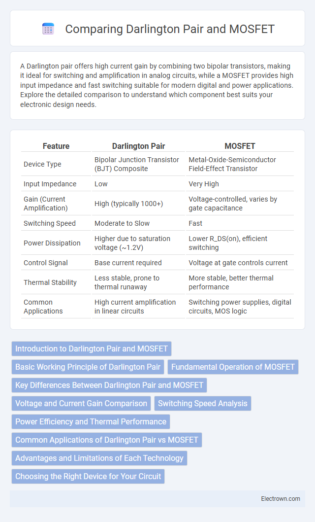
| Feature | Darlington Pair | MOSFET |
|---|---|---|
| Device Type | Bipolar Junction Transistor (BJT) Composite | Metal-Oxide-Semiconductor Field-Effect Transistor |
| Input Impedance | Low | Very High |
| Gain (Current Amplification) | High (typically 1000+) | Voltage-controlled, varies by gate capacitance |
| Switching Speed | Moderate to Slow | Fast |
| Power Dissipation | Higher due to saturation voltage (~1.2V) | Lower R_DS(on), efficient switching |
| Control Signal | Base current required | Voltage at gate controls current |
| Thermal Stability | Less stable, prone to thermal runaway | More stable, better thermal performance |
| Common Applications | High current amplification in linear circuits | Switching power supplies, digital circuits, MOS logic |
Introduction to Darlington Pair and MOSFET
A Darlington pair consists of two bipolar junction transistors (BJTs) connected to provide high current gain, making it ideal for applications requiring amplified current from a low input signal. MOSFETs (Metal-Oxide-Semiconductor Field-Effect Transistors) operate with voltage control over current flow and offer high input impedance and fast switching speeds, suitable for power switching and amplification. Understanding the fundamental differences between Darlington pairs and MOSFETs helps you choose the right transistor technology for efficient signal amplification or switching in your electronic circuits.
Basic Working Principle of Darlington Pair
A Darlington pair consists of two bipolar junction transistors (BJTs) connected to provide high current gain by cascading the current amplification stages. The input transistor amplifies the base current, which then drives the second transistor, resulting in a combined current gain approximately equal to the product of the individual gains. This configuration allows the Darlington pair to switch larger loads with a low input current, making it efficient for applications requiring high gain and moderate switching speeds compared to single BJTs or MOSFETs.
Fundamental Operation of MOSFET
MOSFETs operate by controlling the voltage applied to the gate terminal, which modulates the conductivity of a semiconductor channel between the source and drain, enabling efficient switching and amplification. Unlike Darlington pairs that rely on two bipolar junction transistors (BJTs) in a cascade to achieve high current gain, MOSFETs provide high input impedance and faster switching speeds due to their voltage-driven operation. Your choice of MOSFET ensures lower power dissipation and enhanced control in high-frequency or power-sensitive applications.
Key Differences Between Darlington Pair and MOSFET
The key differences between a Darlington pair and a MOSFET lie in their structure and operation: a Darlington pair consists of two bipolar junction transistors (BJTs) connected to provide high current gain, whereas a MOSFET is a single transistor with voltage-controlled gate and high input impedance. Darlington pairs typically exhibit higher saturation voltage and slower switching speeds compared to MOSFETs, which offer faster switching and greater efficiency in power applications. Your choice depends on the specific need for current gain versus switching speed and efficiency in your circuit design.
Voltage and Current Gain Comparison
A Darlington pair offers high current gain, often exceeding 1000, by cascading two bipolar transistors, which makes it suitable for amplifying weak signals with minimal input current. MOSFETs, on the other hand, provide voltage gain primarily through their transconductance but usually have lower current gain compared to a Darlington pair. For your applications requiring strong current amplification, a Darlington pair excels, while MOSFETs are preferable when high input impedance and voltage control are critical.
Switching Speed Analysis
Darlington pairs exhibit slower switching speeds due to their high current gain but significant charge storage and saturation voltage, causing longer turn-off times. MOSFETs offer superior switching performance with low gate charge and near-instantaneous voltage control, leading to faster turn-on and turn-off transitions. For high-frequency applications, MOSFETs outperform Darlington pairs in minimizing switching losses and thermal dissipation.
Power Efficiency and Thermal Performance
Darlington pairs exhibit higher voltage drop due to the series connection of two transistors, resulting in lower power efficiency compared to MOSFETs, which have significantly lower on-resistance and therefore dissipate less power during conduction. Thermal performance favors MOSFETs as their lower power loss reduces heat generation, allowing for more effective thermal management and potentially smaller heat sinks. When optimizing Your circuit for power efficiency and thermal stability, choosing a MOSFET often yields superior performance over a Darlington pair.
Common Applications of Darlington Pair vs MOSFET
Darlington pairs are commonly used in applications requiring high current gain such as audio amplifiers, relay drivers, and motor control circuits where switching speed is less critical. MOSFETs excel in high-speed switching applications like power supplies, DC-DC converters, and RF amplifiers due to their fast switching characteristics and high input impedance. Your choice depends on whether you prioritize current gain and linear amplification (Darlington pair) or efficiency and switching speed (MOSFET).
Advantages and Limitations of Each Technology
Darlington pairs offer high current gain and simplicity in driving heavy loads, making them ideal for low-frequency analog applications, but suffer from increased voltage drop and slower switching speeds. MOSFETs provide superior switching speed, higher efficiency, and lower on-resistance, which benefits high-frequency and power-sensitive circuits, yet they require careful gate drive design and can be more susceptible to static damage. Both devices have unique advantages: Darlington pairs excel in cost-effective linear amplification, while MOSFETs dominate in switching and efficiency-critical roles.
Choosing the Right Device for Your Circuit
When selecting between a Darlington pair and a MOSFET for your circuit, consider the Darlington pair's high current gain and ease of use in low-voltage applications versus the MOSFET's superior efficiency and faster switching speeds. MOSFETs provide lower on-resistance and higher input impedance, making them ideal for power-efficient designs and high-frequency switching operations. Darlington pairs are preferred in cost-sensitive, low-frequency applications where complexity and size are less critical.
Darlington pair vs MOSFET Infographic